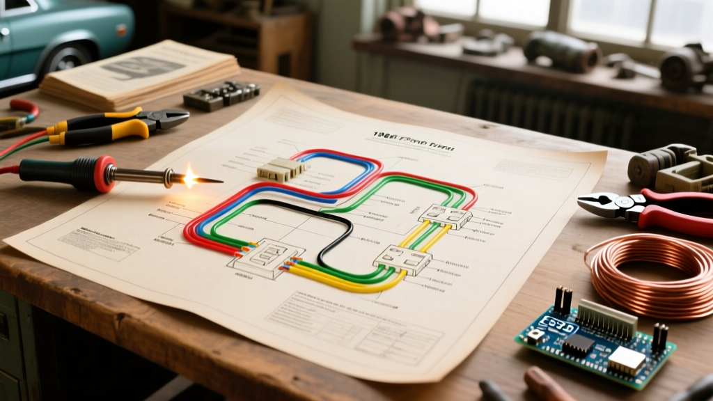

The Core Architecture of the 1966 Mustang Electrical System
Restoring or modifying a classic pony car requires a deep understanding of its foundational electrical layout. When analyzing 1966 Mustang wiring diagrams electrical schematics, you are looking at a pivotal transition year for Ford. The 1966 model year standardized the alternator (replacing the generator found on early 1965 models) and introduced a standard ammeter in the dash pod, replacing the simplistic charge indicator light. Furthermore, 1966 marked the debut of the dash-mounted four-way emergency hazard flasher switch, a feature that significantly altered the steering column turn signal cam and dash harness routing.
To successfully navigate these schematics, you must understand that the factory harness is divided into four primary sub-assemblies: the main dash harness, the engine feed harness, the forward lamp harness, and the taillight harness. Unlike modern vehicles that utilize multiplexed CAN-bus systems, the 1966 Mustang relies on a dedicated, point-to-point copper wire network. This means every single component has a dedicated power and ground path, making the 1966 Mustang wiring diagrams highly linear but physically bulky.
Decoding Factory Schematics: Wire Color Codes and Gauges
Ford utilized a highly specific color-coding system in the 1960s, relying on a primary base color with a secondary tracer (hash) stripe. When reading the schematics, the wire gauge (AWG) is just as critical as the color, as it dictates the current-carrying capacity of the circuit. Below is a reference matrix for the most critical circuits found in the 1966 Mustang engine and dash harnesses.
| Wire Color (Base / Tracer) | Gauge (AWG) | Circuit Function | Max Ampacity (Stock) |
|---|---|---|---|
| Yellow / Black Hash | 10 AWG | Main Battery Feed to Ammeter | 30A - 40A |
| Black / Yellow Hash | 14 AWG | Headlight Switch to Floor Dimmer | 15A |
| Green / Black Hash | 18 AWG | Left Rear Turn Signal / Stop Lamp | 6A |
| White / Blue Hash | 18 AWG | High Beam Indicator Light (Dash) | 3A |
| Red / Black Hash | 12 AWG | Alternator Output to Ammeter | 20A - 30A |
Expert Insight: When tracing a 1966 schematic, always remember that Ford's factory diagrams show the wires in their "unwrapped" state. In reality, the harness is wrapped in non-adhesive friction tape or corrugated loom. If a wire shows as Green/Black on the diagram but appears solid green in your car, the tracer stripe has likely faded due to 50+ years of engine bay heat and chemical exposure.
Common Failure Modes and Troubleshooting the '66 Harness
Decades of thermal cycling, vibration, and aftermarket modifications lead to specific, predictable failure points in the 1966 Mustang electrical system. Understanding these edge cases will save you hours of diagnostic time.
The Notorious Headlight Switch Meltdown
The most common catastrophic failure in a first-generation Mustang is the melting of the headlight switch plug and the internal fatigue of the switch's thermal circuit breaker. The stock sealed-beam headlights draw approximately 4.5 amps each (9A total for low beams, 12A+ for high beams). However, many restorers upgrade to halogen H4 bulbs, which can draw 15 amps per bulb. This 30-amp draw passes directly through the 50-year-old copper contacts of the headlight switch, causing extreme resistance, heat, and eventually melting the plastic connector housing.
The Fix: Do not simply replace the switch. Install a heavy-duty headlight relay upgrade. Using a standard 30A Bosch-style relay (Part #0332014150), you can route the heavy 10 AWG battery current directly from the starter solenoid to the headlights, using the factory headlight switch only as a low-amp trigger signal. This drops the load on the dash harness from 25+ amps down to less than 1 amp, completely eliminating the melting hazard.
Thermal Flasher Incompatibility with LED Conversions
The 1966 Mustang utilizes a thermal bimetallic flasher can (Ford Part #C8AZ-13350-A) located under the dash on the driver's side. This component relies on the heat generated by the electrical resistance of incandescent bulbs to bend a metal strip and break the circuit, creating the "blink." If you upgrade your taillights to modern LED boards, the current draw drops from ~4 amps to less than 0.5 amps. The thermal flasher will not generate enough heat to cycle, resulting in solid illumination without blinking. You must replace the thermal unit with an electronic LED flasher (such as the Trico EF32RL or a generic 3-pin solid-state flasher) to restore proper operation.
Restoration vs. Upgrading: Harness Replacement Matrix
When your factory harness exhibits brittle insulation, cracked loom, or previous "hacks" (like spliced-in speaker wire), you face a critical decision: restore to factory specifications or upgrade to a modern fused system. Below is a comparison of the two primary paths available in 2026.
| Feature | OEM Reproduction Harness (e.g., NPD / CJ Pony) | Modern Aftermarket Kit (e.g., American Autowire / Painless) |
|---|---|---|
| Average Cost | $180 - $260 | $450 - $750 |
| Connector Types | Factory Molded Plastic & Bullet Connectors | Modern Weather-Pack & Deutsch Connectors |
| Fuse Technology | Glass Tube (SFE/AGC) - Factory Style | Modern ATO/ATC Blade Fuses |
| Circuit Count | 12 to 14 Circuits (Stock) | 18 to 22 Circuits (Expanded for A/C, EFI, Audio) |
| Best Application | Concours Restorations, MCA Judged Cars | Restomods, EFI Swaps, High-Draw Audio Systems |
If you are building a restomod with a Coyote V8 swap, electric cooling fans, and a modern digital dash, an OEM reproduction harness will fail to support the amperage requirements. In these cases, sourcing a complete chassis kit from manufacturers like American Autowire is mandatory. These kits replace the archaic glass fuse block with a centralized, modern blade-fuse panel and include dedicated high-amp relays for electric fans and fuel pumps.
Essential Tools for Schematic Tracing and Repair
Working on a 50-year-old wiring harness requires more than a basic test light. To properly diagnose voltage drops and trace hidden shorts behind the dash, equip your bench with the following professional tools:
- True-RMS Digital Multimeter: A high-quality meter like the Fluke 115 is essential for accurately measuring voltage drop across the ammeter shunt and headlight switch. Cheap meters often misread low-resistance DC circuits.
- Power Probe / Circuit Tester: A Power Probe IV allows you to inject 12V power or ground directly into a circuit while monitoring the amperage draw in real-time. This is invaluable for testing the windshield wiper motor and heater blower motor without dismantling the dash.
- Tone Generator and Inductive Amplifier: When a wire is broken inside the harness wrap behind the firewall, a Fox and Hound tone generator will allow you to trace the exact path of the wire without piercing the insulation.
- Wire Depinning Tools: Never cut wires to replace a terminal. Use specific extraction tools to release the locking tangs on the factory molded connectors, allowing you to crimp on new brass terminals and reuse the original plastic housings.
Sourcing Accurate Documentation
Do not rely on generic internet forums for your primary schematic references. Factory errors were common in early print runs, and modified diagrams often circulate online. For the most accurate 1966 Mustang wiring diagrams electrical schematics, always cross-reference your work with the official 1965-1973 Ford Mustang Shop Manual (specifically Volume 2, Section 17 for Electrical). Additionally, major restoration suppliers like National Parts Depot provide highly accurate, updated wiring schematics with their reproduction harnesses, which often include factory errata corrections that Ford issued in late 1966.
Final Thoughts on 1966 Electrical Integrity
The 1966 Mustang represents a golden era of analog automotive engineering. Its electrical system is robust, logical, and entirely repairable if you respect the original design parameters. By understanding the specific color codes, anticipating the thermal failure points of the headlight and turn signal circuits, and knowing when to integrate modern relays, you can ensure your classic pony car remains reliable on the road for decades to come. Always trace your circuits methodically, verify your grounds to bare metal, and let the schematics guide your wrench.