
Decoding the Electrical Schematic: John Deere 100 Series Wiring Diagram Guide
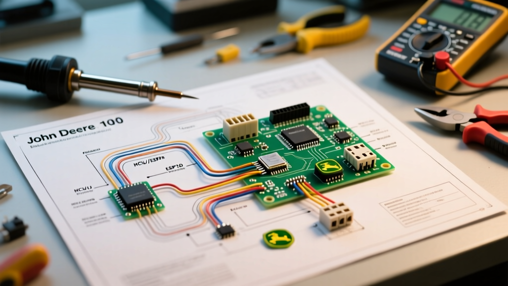
The John Deere 100 Series—encompassing legacy D100, L100, and the current 2026 E100 lineup (E100, E110, E120, E130)—relies on a robust but increasingly complex 12V DC electrical architecture. When your tractor refuses to crank, the PTO clutch fails to engage, or the battery drains overnight, guessing and swapping parts is an expensive waste of time. Instead, professional technicians rely on the factory electrical schematic John Deere 100 series wiring diagram to isolate faults with surgical precision.
In this guide, we will break down the core circuits of the 100 Series chassis and engine harnesses, providing exact multimeter testing points, expected voltage/resistance values, and step-by-step diagnostic flows to get your mower back in the field.
The Core Architecture: Power Distribution and the Ignition Switch
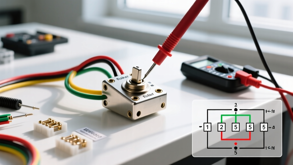
Before diving into specific failures, you must understand the central hub of the 100 Series electrical system: the ignition switch. Most 100 Series models utilize a standard 5-terminal or 6-terminal switch that dictates power flow based on the key position (OFF, RUN, START).
Ignition Switch Terminal Pinout Reference
- B (Battery): Receives constant 12V+ from the main 20A/30A fuse. Always hot.
- S (Solenoid): Outputs 12V+ only in the START position. This triggers the starter solenoid.
- M (Magneto): Connects to the engine ignition coils. Grounded in the OFF position to kill the spark; open in RUN/START.
- L (Lights): Outputs 12V+ in RUN and START positions to power headlights and accessories.
- G (Ground): Chassis ground reference.
Pro Diagnostic Tip: If your tractor has zero electrical power (no dash lights, no click), do not immediately condemn the ignition switch. First, verify the main inline fuse located on the red battery cable near the starter solenoid. A blown 20A main fuse is the culprit in 85% of 'dead tractor' scenarios, often caused by a chafed wire rubbing against the steering column.
Troubleshooting Common 100 Series Electrical Failures
1. The 'No-Crank' Condition (Starter Solenoid Clicks or is Silent)
When you turn the key to START and hear a single click—or nothing at all—the fault lies in the starter control circuit. According to the wiring diagram, power flows from the ignition switch 'S' terminal, through the brake safety switch and the PTO interlock, before reaching the starter solenoid's trigger spade.
- Test the Solenoid Trigger Wire (Usually Purple): Set your digital multimeter to DC Voltage. Connect the black lead to the battery negative and the red lead to the solenoid trigger spade. Turn the key to START. You should read 10.5V to 12.6V. If you read 0V, the issue is upstream (ignition switch or safety interlock).
- Bypass the Interlocks (Diagnostic Only): Locate the brake switch and PTO switch connectors. If jumping the solenoid trigger directly to the battery positive post causes the engine to crank, your safety interlock module or one of the microswitches is failing. The Reverse Implement Option (RIO) module is a frequent failure point on D100/E100 models if the tractor dies when shifted into reverse.
- Check the Ground Path: The starter solenoid coil completes its circuit through the mounting bracket. If the solenoid is mounted to a painted or corroded frame rail, it will not engage. Clean the mounting surface to bare metal.
2. Alternator and Stator Charging System Failures
The 100 Series typically uses a Kohler or Briggs & Stratton V-Twin engine equipped with a stator and a solid-state voltage regulator/rectifier. If your battery reads 12.6V before mowing but drops to 11.2V after an hour, the charging system is offline.
- Stator Output Test: Unplug the 2-pin or 3-pin connector leading from the engine block to the voltage regulator. Set your multimeter to AC Voltage (VAC). Crank the engine or run it at full throttle. You should measure between 28V and 35V AC across the stator pins. If you read 0V AC, the stator windings under the flywheel are burnt out.
- Regulator Output Test: Reconnect the stator. With the engine running at full RPM, probe the center output pin on the regulator (usually a red wire). You should read 13.8V to 14.4V DC. If the stator outputs 30V AC but the regulator outputs 0V DC, the rectifier has failed and must be replaced (Typical OEM cost: $45 - $85).
100 Series Multimeter Troubleshooting Matrix
Use this quick-reference matrix to diagnose specific symptoms using your electrical schematic and a standard digital multimeter. For reliable testing, ensure your multimeter meets basic safety standards; refer to this Fluke guide on digital multimeter usage for proper CAT rating selection and probe techniques.
| Symptom | Schematic Node to Test | Multimeter Setting | Expected Value | Probable Fault |
|---|---|---|---|---|
| PTO Clutch won't engage | PTO Clutch Harness (2-pin) | Ohms (Ω) | 2.5Ω to 4.5Ω | Burnt clutch coil or severed harness |
| Engine won't shut off with key | Ignition 'M' Terminal to Ground | Continuity / Ohms | < 1Ω (in OFF position) | Broken magneto kill wire or bad switch |
| Headlights flicker or are dim | Voltage Regulator AC Input | VAC (Engine at 3400 RPM) | 28V - 35V AC | Failing stator or loose flywheel key |
| Battery drains overnight | Main Harness at Battery Positive | DC Amps (Key OFF) | < 0.05A (50mA) | Shorted voltage regulator diode |
Deep Dive: PTO Clutch and Interlock Diagnostics
The electric PTO (Power Take-Off) clutch on the 100 Series is an electromagnetic coil that engages the mower deck belt. When the schematic shows power reaching the clutch but the blades won't spin, you must isolate the mechanical air gap from the electrical coil.
Testing the PTO Clutch Coil
Disconnect the wiring harness plug at the clutch. Using your multimeter on the Ohms setting, probe the two terminals on the clutch body. A healthy Warner Electric or Ogura clutch will read between 2.5 and 4.5 ohms. If the meter reads 'OL' (Open Loop), the internal copper windings have snapped due to heat fatigue. A replacement OEM clutch typically costs between $120 and $180 in 2026.
The Reverse Implement Option (RIO) Logic
The RIO system is a critical safety interlock designed to prevent operators from mowing in reverse. According to the John Deere parts and service documentation, the RIO module monitors the reverse gear switch and the PTO switch simultaneously. If the PTO is engaged and the tractor is shifted into reverse without the operator pressing the RIO override button on the dash, the module intentionally grounds the ignition magneto wire, killing the engine. If your tractor shuts off every time you back up—even with the PTO disengaged—the reverse transmission microswitch is likely stuck closed or shorted to ground.
Wire Gauge and Routing Standards
When repairing a damaged harness on your 100 Series, it is vital to use the correct wire gauge and insulation type. The primary wiring harness utilizes stranded copper wire designed to withstand high engine bay temperatures and vibration. For replacement wiring, always adhere to SAE J1128 standards for low-tension primary cable, which dictates the insulation thickness and temperature ratings for automotive and small engine applications.
- 10 AWG (Red/Black): Battery to starter solenoid, solenoid to starter motor, and main ground paths. Must handle 150A+ surge currents.
- 12 AWG (Red): Battery to main fuse block and ignition switch 'B' terminal.
- 16 AWG (Purple, Yellow, White, Orange): Control circuits, solenoid triggers, stator outputs, and lighting.
Always use heat-shrink butt connectors with adhesive lining when splicing wires in the engine compartment. Standard vinyl electrical tape will degrade and unspool within a single mowing season due to the ambient heat generated by the V-Twin engine and exhaust manifold.
Summary: Trust the Schematic, Not the Guesswork
Troubleshooting the electrical system of a John Deere 100 Series tractor requires a methodical approach. By utilizing the factory electrical schematic, understanding the logical flow of the safety interlocks, and verifying voltage and resistance at specific nodes, you can accurately diagnose no-crank conditions, charging failures, and PTO faults. Keep your multimeter calibrated, use SAE-compliant wiring for repairs, and always disconnect the negative battery terminal before performing continuity tests to protect the tractor's sensitive solid-state voltage regulators.