
Understanding Kenmore Dryer Manufacturing Lineages
Before interpreting any wiring diagram for Kenmore dryer models, you must understand that Kenmore is a Sears house brand, not a manufacturer. The actual wiring schematics depend entirely on the original equipment manufacturer (OEM). Identifying your dryer's OEM is the critical first step in any electrical troubleshooting or power cord installation.
| Model Prefix | OEM Manufacturer | Common Wiring Characteristics |
|---|---|---|
| 110.xxxxx | Whirlpool / Maytag | Standard 3-terminal block; L2 routes through motor centrifugal switch to heater. |
| 417.xxxxx | Frigidaire / Electrolux | Often uses direct-wire terminal blocks; electronic control boards common in Elite series. |
| 790.xxxxx | Frigidaire | Similar to 417 series; distinct thermal limiter wiring on the heater housing. |
| 628.xxxxx | Whirlpool (Older) | Mechanical timer circuits; simpler wiring harnesses with fewer solid-state relays. |
Most modern Kenmore Elite and standard electric dryers sold in the last decade are Whirlpool-manufactured (110 prefix). The wiring diagrams for these units follow a highly standardized pattern, which we will break down step-by-step below.
3-Prong vs. 4-Prong: NEC Code Requirements
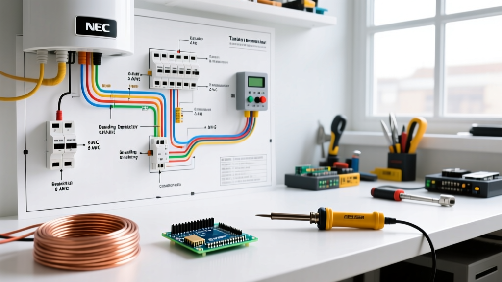
The National Electrical Code (NEC) mandated a shift from 3-prong to 4-prong receptacles for new construction starting in 1996. According to the National Fire Protection Association (NFPA), this change was implemented to separate the equipment grounding conductor from the neutral conductor, significantly reducing the risk of stray voltage on the dryer chassis.
NEC Article 250.140 Exception: For existing pre-1996 installations, you are legally permitted to use a 3-prong cord on a new dryer, provided you install the bonding strap connecting the neutral terminal to the chassis ground. However, upgrading the wall receptacle to a 4-prong NEMA 14-30R is always the recommended safety best practice.
Step-by-Step Walkthrough: Wiring a 4-Prong Power Cord
A 4-prong cord (NEMA 14-30P) features four wires: Black (Hot 1), Red (Hot 2), White (Neutral), and Green (Ground). You will need a 10 AWG, 30-amp rated cord and a 1/4-inch nut driver.
Step 1: Access the Terminal Block and Strain Relief
- Unplug the dryer and pull it away from the wall.
- Remove the 5/16-inch hex screws securing the lower access panel or the upper rear panel, depending on your specific 110.xxxx model.
- Loosen the strain relief clamp at the bottom of the terminal block cutout.
Step 2: Connect the Neutral (White) Wire
Route the white wire through the strain relief. Connect it to the center terminal (usually marked with a silver or white-colored screw). Tighten the screw to approximately 15-20 in-lbs. Ensure no copper strands are splayed outside the terminal clamp.
Step 3: Connect the Hot Legs (Black and Red)
Connect the black wire to the left outer terminal and the red wire to the right outer terminal. On a 240V split-phase system, the polarity of the hot legs does not matter, but maintaining Black-Left and Red-Right aligns with standard electrical diagram conventions.
Step 4: Connect the Equipment Ground (Green)
This is the most critical safety step. Attach the green wire to the chassis ground screw, which is typically a green-painted hex screw located just below the terminal block on the metal dryer cabinet. Do not attach the green wire to the center neutral terminal.
Step 5: Remove the Bonding Strap (Crucial)
Inspect the center neutral terminal. If a small copper or white bonding wire/strap is connecting the center terminal to the metal chassis, you must remove it or fold it back and cap it. In a 4-prong setup, the neutral and ground must remain strictly separated.
Step-by-Step Walkthrough: Wiring a 3-Prong Power Cord
If you live in an older home with a NEMA 10-30R receptacle, you will use a 3-prong cord (Black, Red, White). The outer hot wires connect to the outer terminals exactly as described above. The white wire connects to the center neutral terminal.
The Grounding Strap Requirement: Because there is no dedicated green ground wire in a 3-prong cord, the dryer's metal chassis must be bonded to the neutral. You must ensure the factory-installed bonding strap (or a dedicated 10 AWG bonding wire) connects the center neutral terminal directly to the chassis ground screw. Failure to do this will leave the dryer chassis ungrounded, creating a lethal shock hazard if an internal short occurs.
Internal Wiring Diagram Tracing: Motor and Heater Circuits
When reading the internal wiring diagram (usually tucked inside the dryer's front console or rear panel), you must understand the safety interlock circuit. In Whirlpool-built Kenmore dryers, the heating element does not receive power unless the drive motor is running.
- L1 Leg (Red/Black): Routes from the terminal block, through the thermal fuse, through the high-limit thermostat, through the operating thermostat (or thermistor), and into the heating element.
- L2 Leg (Red/Black): Routes from the terminal block into the drive motor's centrifugal switch. When the motor reaches roughly 1,200 RPM, the centrifugal switch closes, allowing L2 voltage to pass through to the other side of the heating element.
This design ensures that if the motor belt breaks or the motor fails, the centrifugal switch opens, cutting power to the heater to prevent a fire. According to the U.S. Fire Administration (USFA), failure to clean lint and improper electrical bypassing of these thermal safeties are leading causes of the 2,900 annual dryer fires in the United States.
Troubleshooting Common Wiring & Component Failures
Use a digital multimeter set to the Ohms (Ω) or continuity setting to diagnose internal wiring faults. Always disconnect power before testing.
| Symptom | Suspect Component / Wiring Node | Expected Multimeter Reading | Failure Mode Reading |
|---|---|---|---|
| Dryer runs, but no heat | Heating Element Assembly | 8 to 12 Ω | OL (Open Loop / Infinite) |
| Dryer runs, but no heat | Thermal Fuse (on blower housing) | 0 Ω (Continuity) | OL (Blown fuse) |
| Dryer won't start, no click | Door Switch / Start Switch wiring | 0 Ω when depressed | OL when depressed |
| Dryer heats, but motor won't run | Motor Centrifugal Switch / Relay | Check board relay outputs | No 120V at motor L2 pin |
| Breaker trips immediately | Heater shorted to chassis | OL between heater coil and casing | 0 Ω (Dead short to ground) |
Pro-Tip: Verifying Receptacle Voltage
Before plugging in your newly wired Kenmore dryer, use your multimeter to test the wall receptacle. Set the meter to AC Voltage (V~).
• Measure Hot to Hot (Left slot to Right slot): You should read 220V to 240V.
• Measure Hot to Neutral (Left to Center, or Right to Center): You should read 110V to 120V.
• Measure Neutral to Ground (Center to Ground/U-shape on 4-prong): You should read less than 2V. If you read 120V here, your wall receptacle is miswired, and plugging in the dryer will destroy the electronic control board.
Final Safety Checks and Code Compliance
After completing the terminal block wiring, gently tug on each wire to ensure the terminal clamps are secure. Loose connections on a 30-amp, 240V circuit will create high resistance, leading to arcing, melted terminal blocks, and potential electrical fires. Replace any terminal block that shows signs of scorching or pitting (OEM replacement part #279320 for most Whirlpool-built Kenmore models, typically costing around $15 to $22).
Always verify that your home's electrical panel features a dedicated 30-amp, double-pole breaker for the dryer circuit. Never upsize the breaker to 40A or 50A to stop nuisance tripping; if a 30A breaker trips, you have an internal short or a failing motor drawing locked-rotor amperage (LRA). For detailed OEM schematics specific to your exact serial number, cross-reference your model on Sears PartsDirect or consult the manufacturer's service manual tucked inside the dryer's control console.