
Understanding the 12V DC LED Circuit Architecture
Designing a reliable 12V DC lighting system for an RV, camper van, or off-grid cabin requires more than just connecting positive and negative wires. Unlike 120V AC household wiring, 12V DC systems operate at a much lower voltage, meaning they draw significantly higher current to produce the same wattage. This makes voltage drop and proper circuit protection the most critical factors in your wiring diagram for 12V LED lights. According to the NFPA 1192 Standard on Recreational Vehicles, all DC circuits must be protected by overcurrent devices (fuses or breakers) rated for the specific wire gauge used, ensuring that a short circuit never leads to a thermal event.
Modern 12V LEDs are incredibly efficient. As noted by the U.S. Department of Energy, LED lighting uses at least 75% less energy than incandescent lighting. A typical 18W LED puck light draws a mere 1.5 amps at 12V, allowing you to wire multiple fixtures on a single circuit. However, the low voltage means that even a 0.5V drop across a long, undersized wire run will result in noticeable dimming and reduced lifespan of the LED driver.
The Master Wiring Diagram for 12V LED Lights
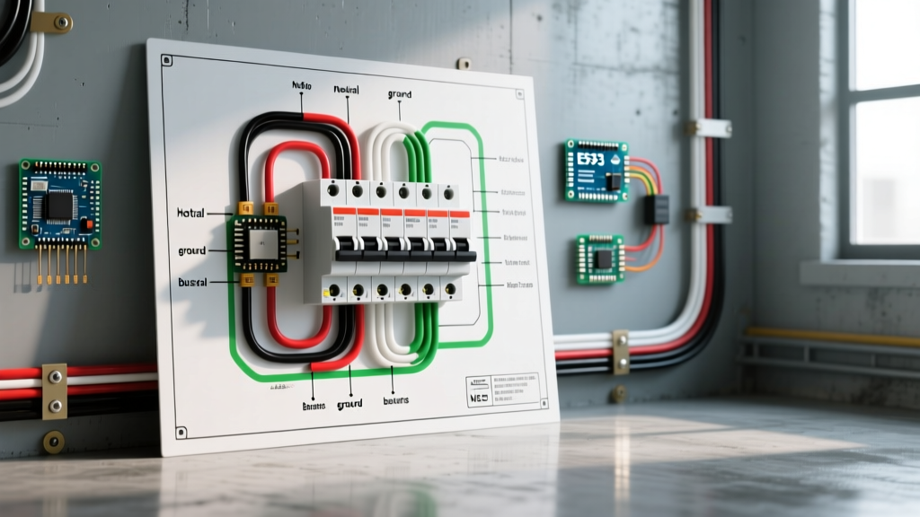
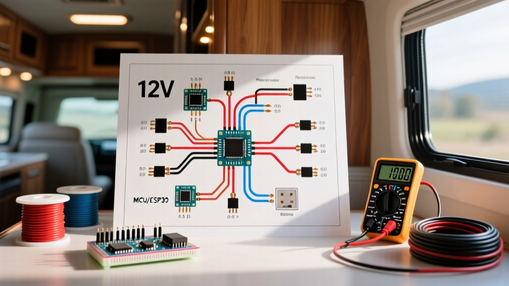
Below is the logical node flow for a professional-grade 12V LED lighting circuit. This topology ensures centralized circuit protection, clean switching, and a dedicated ground return path.
Circuit Node Flow (Schematic Representation)
- Power Source: 12V LiFePO4 or AGM Battery Bank
- Main Disconnect: High-Amp Battery Kill Switch (e.g., 250A Continuous)
- Positive Distribution: Blue Sea Systems ST Blade Fuse Block (Fused at 10A for lighting branch)
- Branch Circuit (Hot): 14 AWG or 12 AWG stranded copper wire
- Switching: Single Pole Single Throw (SPST) Rocker Switch
- Load: 12V LED Light Fixtures (Wired in Parallel)
- Ground Return: Negative Busbar (Never use the vehicle chassis as a ground return for sensitive LED electronics)
- Return to Source: Heavy gauge wire from Negative Busbar back to Battery Negative
Wire Gauge Sizing and Voltage Drop Matrix
The most common failure in DIY 12V LED installations is end-of-run dimming. This occurs when the wire resistance causes the voltage at the furthest LED fixture to drop below 11.5V. To prevent this, we use the 3% voltage drop rule. The table below provides exact wire gauge requirements based on total circuit amperage and the one-way distance from the fuse block to the furthest fixture.
| Wire Gauge (AWG) | Max Ampacity (Chassis) | Max Run Length (3% Drop at 5A) | Max Run Length (3% Drop at 10A) | Recommended Fuse Size |
|---|---|---|---|---|
| 16 AWG | 10 Amps | 7.5 feet | 3.5 feet | 5A or 7.5A |
| 14 AWG | 15 Amps | 12 feet | 6 feet | 10A |
| 12 AWG | 20 Amps | 20 feet | 10 feet | 15A or 20A |
| 10 AWG | 30 Amps | 32 feet | 16 feet | 25A or 30A |
Pro Tip: Always measure the total wire length (positive + negative return) when calculating voltage drop manually, as the current must travel the full loop. For most standard camper conversions, running a 12 AWG backbone and dropping down to 14 AWG for individual fixture pigtails is the most cost-effective and reliable strategy.
Component Selection: Beyond the Basics
Selecting the right hardware ensures your wiring diagram translates into a safe, long-lasting physical installation.
- Fuse Block: Avoid cheap, unbranded Amazon fuse blocks that suffer from high internal resistance and loose blade contacts. Invest in the Blue Sea Systems 5025 ST Blade Fuse Block (approx. $48 in 2026). It features tin-plated copper buses and independent circuit protection.
- Connectors: Ditch the twist-on wire nuts and electrical tape. Use WAGO 221 Lever-Nuts (approx. $0.45 each). They provide a gas-tight, vibration-proof connection that is easily inspectable and reusable. For high-vibration areas near the alternator or wheel wells, use adhesive-lined heat shrink crimps (Ancor brand).
- Switches: Standard automotive toggle switches are prone to moisture ingress. Use Carling V-Series Contura Rocker Switches. They are IP68 sealed and feature a satisfying tactile snap.
- LED Fixtures: Ensure your 12V LEDs have built-in constant-current drivers. Cheap LEDs use simple resistors, meaning they will burn brighter (and hotter) when your alternator pushes 14.4V, and dim when the battery drops to 12.0V. Brands like Nilight or Acegoo feature wide-input drivers (10V-18V) that maintain consistent brightness regardless of battery state-of-charge.
Step-by-Step Execution Guide
Phase 1: Planning and Routing
Map out your fixture locations on a digital or paper floor plan. Calculate the total wattage for each zone (e.g., Kitchen, Bedroom, Exterior Awning). Divide the total wattage by 12V to find the amperage. Add a 20% safety margin to determine your wire gauge and fuse size. Run your wire looms through corrugated split-loom tubing to protect against chafing against sharp metal chassis edges.
Phase 2: Termination and Fusing
Terminate all positive wires at the Blue Sea fuse block. Never route unfused positive wires more than 7 inches from the battery source. If your fuse block is mounted further than 7 inches from the battery, you must install a primary Class T or ANL fuse within 7 inches of the battery positive terminal. Connect all negative wires to a dedicated negative busbar, then run a single, heavy-gauge wire (e.g., 2/0 AWG) from the busbar to the battery negative.
Phase 3: Parallel Load Wiring
When wiring multiple LED puck lights or strip lights, always wire them in parallel, never in series. Wiring in series will divide the voltage across the fixtures, resulting in severely dimmed lights and potential damage to the LED drivers. Use WAGO connectors inside accessible junction boxes (like the Carling switch bezel housings) to branch the hot and ground wires to each individual fixture.
Advanced Troubleshooting & Edge Cases
Even with a perfect wiring diagram for 12V LED lights, real-world installations can present unique electrical gremlins. Here is how to diagnose the most common edge cases:
The 'Ghosting' Phenomenon
Symptom: Your LED lights emit a faint glow even when the wall switch is turned completely off.
Cause: This is almost always caused by using a rocker switch with an internal neon or LED indicator light. The indicator light requires a tiny amount of current (micro-amps) to illuminate, which leaks through the circuit and is enough to excite the highly efficient phosphors in modern 12V LEDs.
Solution: Replace the switch with a non-illuminated model, or solder a 10k-ohm, 1/2W bleeder resistor across the positive and negative terminals of the LED load to absorb the parasitic micro-current.
Flickering Under Load
If your 12V LEDs flicker when the RV water pump or compressor fridge kicks on, you are experiencing severe voltage sag. These inductive appliances draw massive inrush currents (up to 60A for a split-second), dragging the entire 12V bus voltage down to 10V or lower. To fix this, ensure your lighting circuit is on a dedicated branch separate from heavy inductive loads, and verify that your main battery busbars are oversized (e.g., Blue Sea 250A busbars) to minimize systemic resistance.
PWM Dimmer Interference
If you are integrating a 12V PWM (Pulse Width Modulation) dimmer switch into your wiring diagram, ensure the dimmer is rated for the total inductive and capacitive load of your LEDs. Cheap PWM dimmers often fail when subjected to the capacitive inrush of multiple LED drivers, resulting in a high-pitched whining noise or erratic strobing. Always use a dimmer rated for at least 30% more amperage than your calculated total load.
By adhering strictly to this wiring topology, respecting voltage drop calculations, and utilizing marine-grade termination hardware, your 12V LED lighting system will provide brilliant, reliable illumination for years of off-grid adventures.