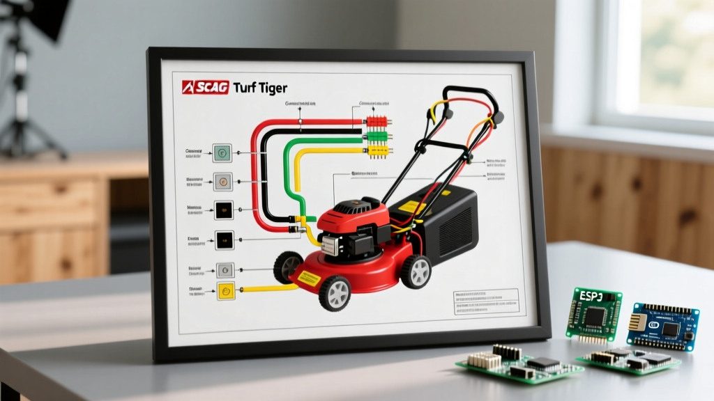

Commercial Zero-Turn Electrical Architecture and Safety
Commercial zero-turn mowers like the Scag Turf Tiger II (STTII) series rely on complex 12V DC electrical systems to manage engine ignition, hydrostatic transmission controls, and electromagnetic Power Take-Off (PTO) clutches. Understanding the wiring diagram for Scag Turf Tiger models is not merely a mechanical exercise; it is a critical safety and compliance requirement for commercial landscaping fleets. In 2026, with commercial equipment utilization rates higher than ever, electrical faults remain a leading cause of sudden blade engagement, hydrostatic lockup, and catastrophic harness fires.
The electrical architecture of models like the STTII-61A-25FX (Kawasaki FX) and the STTII-72V-37CH-EFI (Kohler EFI) integrates high-amperage starter circuits with low-amperage logic circuits. A misinterpretation of the schematic can lead to bypassed safety interlocks, violating federal workplace safety regulations and exposing operators to severe laceration or amputation hazards. This guide dissects the Scag Turf Tiger wiring schematics through the lens of safety, code compliance, and advanced diagnostic troubleshooting.
The Operator Presence Control System (OPCS) Logic
At the core of the Scag Turf Tiger wiring diagram is the Operator Presence Control System (OPCS). This safety interlock network ensures the mower's PTO clutch disengages and the engine shuts down if the operator leaves the seat while the blades are active or the lap bars are in the drive position.
CRITICAL SAFETY WARNING: Bypassing the OPCS seat switch or lap bar relays to 'troubleshoot' a stalling engine is a direct violation of OSHA 29 CFR 1910.212 machine guarding requirements. Commercial fleet managers caught operating modified equipment face severe federal citations and immediate voiding of Scag's liability insurance coverage.
The OPCS relies on a series of normally open (NO) and normally closed (NC) microswitches feeding into a central safety relay module. When the PTO switch is pulled to the 'ENGAGE' position, 12V DC power is routed through the seat switch. If the seat is unoccupied (circuit open), the safety relay immediately drops the ground path to the PTO clutch relay, cutting power to the Warner Electric or Xtreme electromagnetic clutch within milliseconds.
Wire Gauge, Ampacity, and SAE Standards Matrix
When repairing or extending a Scag Turf Tiger harness, technicians must adhere to SAE J1128 standards for low-tension primary cable used in mobile machinery. Using standard building wire (NEC THHN) is strictly prohibited due to its inability to withstand high-frequency vibration, UV exposure, and petroleum-based hydraulic fluid spills common on zero-turn mowers.
| Circuit Function | Standard Wire Color | SAE J1128 Gauge | Max Continuous Ampacity | Fuse / Breaker Rating |
|---|---|---|---|---|
| Battery to Starter Solenoid | Red | 10 AWG (or 6 AWG for long runs) | 40A - 50A | Inline Mega-Fuse (60A) |
| PTO Clutch Engagement | Purple / Red-Tracer | 12 AWG | 20A | 20A Blade Fuse |
| Stator to Voltage Regulator | Yellow (x2 or x3) | 14 AWG | 15A (AC) | Unfused (Stator side) |
| Safety Interlock Logic | Green / White | 18 AWG | 3A | 5A Fuse (Main Ignition) |
| Hydrostat Release Valves | Orange | 16 AWG | 5A | 10A Fuse |
Code Compliance: NFPA 79 and OSHA Mandates
While the National Electrical Code (NEC / NFPA 70) primarily governs stationary building wiring, mobile industrial and commercial groundskeeping equipment falls under the purview of NFPA 79 (Electrical Standard for Industrial Machinery) and OSHA workplace safety mandates. For commercial landscaping businesses, compliance dictates specific wiring practices:
1. Overcurrent Protection Placement
NFPA 79 requires that overcurrent protection devices (fuses or circuit breakers) be installed as close to the power source as practically possible. On the Scag Turf Tiger, the main 20A blade fuse must be located within 18 inches of the starter solenoid's battery terminal. If an aftermarket accessory (e.g., LED light bar or GPS fleet tracker) is spliced into the ignition circuit, it must have its own independent inline fuse placed within 6 inches of the splice point.
2. Connector Sealing and Ingress Protection
Commercial mowers operate in high-moisture, high-debris environments. Splicing wires using twist-on connectors or standard electrical tape is a code violation for mobile equipment. All repairs must utilize heat-shrink solder sleeves with thermoplastic adhesive linings, or sealed Deutsch/Weather-Pack connectors rated for at least IP67 ingress protection. Failure to do so leads to galvanic corrosion, increasing circuit resistance and causing voltage drops that prematurely destroy $450 PTO clutches.
Step-by-Step Troubleshooting: PTO Voltage Drop Testing
A common failure mode in the STTII series is the PTO clutch slipping or failing to engage when the engine is hot. Technicians often misdiagnose this as a burnt clutch coil and order a $400 replacement part. A proper diagnostic flow using the wiring diagram reveals that 80% of these issues are caused by voltage drop across degraded harness connectors.
- Preparation: Set your digital multimeter (DMM) to DC Volts. Ensure the battery is fully charged (minimum 12.6V at rest). Start the engine and run it at full PTO RPM (typically 3600 RPM).
- Source Voltage Check: Probe the battery terminals directly while the PTO is engaged. The voltage regulator should be outputting between 13.8V and 14.4V DC.
- Load Side Check: Move the positive DMM probe to the PTO clutch connector's positive pin (usually the purple wire), and the negative probe to the clutch's ground pin. Do not probe the battery ground for this step.
- Calculate Voltage Drop: Subtract the clutch voltage from the battery voltage. If the battery reads 14.2V and the clutch reads 12.8V, you have a 1.4V drop.
- Evaluate Against Specs: The maximum acceptable voltage drop for a 12V mobile PTO circuit is 0.5V. A drop exceeding 0.5V indicates high resistance in the wiring harness, ignition switch, or safety relay. Clean the Deutsch pins with contact cleaner, crimp new terminals, or replace the OEM harness (Part numbers typically range from $185 to $320 depending on the deck size).
Common Failure Modes & Edge Cases in STTII Harnesses
When reviewing the wiring diagram for Scag Turf Tiger mowers, experienced technicians know to inspect specific 'choke points' where the physical design of the mower subjects the wiring to extreme mechanical stress.
- Hydrostat Pivot Plate Chafing: The main harness routes through the frame near the hydrostatic transmission pivot arms. Over 1,500+ hours of operation, vibration wears through the split-loom conduit and the wire insulation, causing intermittent short-to-ground faults that blow the main 20A ignition fuse. Always inspect this 12-inch section during annual winterization.
- EFI Sensor Ground Loops: On Kohler EFI models (e.g., STTII-72V-37CH-EFI), the ECU requires a dedicated, clean chassis ground. If a technician uses a painted frame bolt to ground an aftermarket accessory, it can create a ground loop that introduces electrical noise into the throttle position sensor (TPS) circuit, causing engine surging.
- PTO Clutch Air Gap Drift: While not strictly a wiring issue, an improperly adjusted PTO clutch air gap (spec is typically 0.018" to 0.022") forces the electromagnetic coil to draw excessive amperage to close the gap. This over-amps the 12 AWG purple wire, melting the fuse block terminals. Always verify air gap with a feeler gauge before condemning the wiring harness.
Frequently Asked Questions (FAQ)
- Where can I find the official OEM wiring schematic for my specific Scag Turf Tiger?
- Scag provides comprehensive, model-specific parts and wiring manuals for free on their official portal. You can download the exact PDF schematic by entering your serial number at the Scag Power Equipment Manuals Page. Never rely on third-party forum diagrams, as wire colors and relay logic change between manufacturing years.
- Is it legal to install an aftermarket kill-switch on a commercial Scag mower?
- Adding a secondary manual kill-switch is permissible under OSHA guidelines as an added safety measure, provided it does not bypass or interfere with the factory OPCS logic. It must be wired in series with the ignition ground kill circuit, utilizing a heavy-duty, weather-sealed toggle switch rated for the alternator's AC ripple current.
- Why does my Scag Turf Tiger blow the PTO fuse only when the deck is lowered into tall, wet grass?
- Wet, dense grass increases the mechanical load on the mower deck spindles. This physical resistance transfers back to the PTO clutch, causing it to slip. A slipping electromagnetic clutch draws spiked, erratic amperage (often exceeding 25A momentarily) as it struggles to maintain magnetic lock, which fatigues and eventually blows the 20A blade fuse. Sharpen the blades, reduce ground speed, and check the clutch air gap before blaming the wiring.
Conclusion: Prioritizing Safety in Fleet Maintenance
Maintaining the electrical system of a Scag Turf Tiger requires strict adherence to the manufacturer's wiring diagrams and overarching safety codes. By respecting SAE wire gauge standards, enforcing OSHA interlock compliance, and utilizing voltage-drop testing over simple continuity checks, commercial fleet managers can eliminate electrical fires, prevent accidental blade engagements, and maximize the operational uptime of their zero-turn mowers. Always consult the official Scag service manuals and adhere to NFPA and OSHA guidelines when performing electrical modifications or repairs.