
Decoding the Wiring Diagram for Ceiling Fan with Remote Systems
Upgrading to a remote-controlled ceiling fan introduces a hidden layer of complexity inside your ceiling canopy: the RF (radio frequency) or IR (infrared) receiver module. While the physical mounting of the fan remains unchanged, the electrical termination requires a precise understanding of both standard residential wire color codes and the proprietary color mappings used by receiver manufacturers like Hunter, Hampton Bay, and Minka-Aire. In 2026, with the rise of ultra-efficient DC motor fans and Matter-compatible smart home integrations, misinterpreting a wiring diagram for ceiling fan with remote configurations can lead to tripped breakers, fried receiver logic boards, or severe fire hazards.
This comprehensive reference guide bridges the gap between your home's branch circuit wiring and the fan's internal receiver harness. We will dissect exact wire gauge requirements based on National Electrical Code (NEC) standards, provide a definitive color code translation matrix, and outline the specific termination hardware required for a safe, long-lasting installation.
Wire Gauge Requirements: Sizing the Branch Circuit
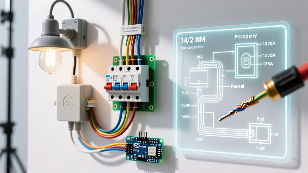
Before touching a single wire nut, you must verify the wire gauge entering your ceiling junction box. The remote receiver itself draws negligible current (typically under 0.1 Amps for the RF module), but the combined load of the fan motor and the light kit dictates the circuit requirements. Furthermore, the wire gauge must strictly match the overcurrent protection device (circuit breaker) supplying the room.
According to the National Fire Protection Association (NFPA 70 / NEC), specifically Article 240.4(D), small conductors have strict ampacity limits to prevent the wire from melting before the breaker trips.
| Breaker Size | Minimum Wire Gauge (Copper) | Max Continuous Load (Watts @ 120V) | Typical Application |
|---|---|---|---|
| 15 Amp | 14 AWG | 1,440W | Dedicated lighting circuits, older homes |
| 20 Amp | 12 AWG | 1,920W | Shared bedroom circuits (lights + receptacles) |
| 15 Amp (Long Run) | 12 AWG (Upsized) | 1,440W | Runs exceeding 75 feet to mitigate voltage drop |
The Color Code Translation Matrix
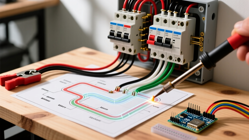
The most common point of failure when following a wiring diagram for ceiling fan with remote setups is the mismatch between house wires, receiver input wires, and receiver output wires. Standard AC motors use a specific color palette, while universal remote receivers (such as the popular Hunter 99119 or Hampton Bay 76273 models, which retail between $45 and $85 in 2026) use their own mapping to separate the light kit from the motor.
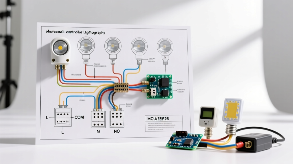
House Wiring to Receiver Input (Canopy Side)
The receiver acts as a gatekeeper. It requires a constant hot and a constant neutral to power its internal RF antenna and logic board, even when the fan is turned "off" via the remote.
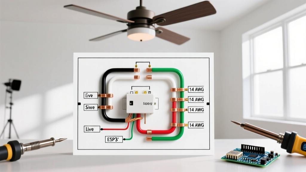
- House Black (Line Hot): Connects to Receiver Black (AC IN L). This is the switched or unswitched hot from your wall switch or breaker.
- House White (Neutral): Connects to Receiver White (AC IN N) AND the Fan/Light White (Neutral Out). The neutral must be pigtailed to complete the 120V circuit for both the receiver and the load.
- House Bare/Green (Ground): Connects directly to the Fan Motor Green and the metal ceiling junction box. Note: Most universal receivers do not have a ground wire; they are double-insulated.
Receiver Output to Fan and Light Kit
Once the receiver processes a signal from the handheld remote, it routes power through internal relays or TRIAC dimmers to the specific output wires.
- Receiver Black (Motor Hot): Connects to the Fan Motor Black (or sometimes Blue, depending on the manufacturer). This powers the main motor coils.
- Receiver Blue (Light Hot): Connects to the Light Kit Blue (or Black with White Stripe). This routes power exclusively to the LED array or incandescent bulbs.
- Receiver White (Neutral Out): Connects to the Fan Motor White and Light Kit White.
Step-by-Step Termination & Hardware Specifics
Proper mechanical termination is just as vital as correct color mapping. The confined space of a standard 4-inch octagon ceiling box requires low-profile connections to prevent pinching the receiver antenna or crushing wire insulation against the metal canopy.
- Strip and Prep: Strip exactly 5/8 inch of insulation from the 14 AWG or 12 AWG house wires. The internal receiver wires are typically 18 AWG stranded. When joining solid house wire to stranded fixture wire, always ensure the stranded wire is twisted tightly and leads the solid wire slightly into the wire nut to prevent the stranded strands from wrapping around the outside of the solid core.
- Connector Selection: Discard the cheap, generic vinyl wire nuts included in the fan box. Use Ideal Twister 341 (Orange) or 3M Performance Plus (Yellow) wire nuts. These feature internal steel coils that bite into both 12 AWG solid and 18 AWG stranded wires simultaneously, preventing the "cold joint" failure mode that causes flickering lights.
- Antenna Placement: The receiver will have a thin, unshielded wire (usually white or grey) that acts as the RF antenna. Do not cut this wire. Route it away from the metal junction box and lay it flat along the top of the receiver module to maximize the 30-foot operational range.
2026 Edge Cases: DC Motors and Smart Fans
The wiring landscape has shifted significantly with the mass adoption of Brushless DC (BLDC) motors. Brands like Big Ass Fans, Modern Forms, and Minka-Aire now dominate the premium market. If you are installing a DC motor fan, the traditional wiring diagram for ceiling fan with remote setups does not apply in the same way.
DC fans contain internal inverters that convert 120V AC to low-voltage DC (usually 24V or 48V). Consequently, the remote receiver is often integrated directly into the motor housing rather than sitting in a bulky canopy module. You will only connect House Black (Hot), House White (Neutral), and Ground. The light kit and motor are controlled via digital data signals over the internal low-voltage harness. Attempting to wire an external universal AC receiver to a DC fan will instantly destroy the fan's internal inverter board, resulting in a $300+ replacement cost.
Furthermore, the U.S. Department of Energy highlights that modern smart fans utilizing Matter-over-Thread or Zigbee protocols require a constant, unswitched 120V supply at the ceiling. If your ceiling box is wired with a traditional "switch loop" (where the white wire is used as a hot and marked with black tape), you will not have a dedicated neutral wire available to power the smart fan's always-on Wi-Fi/Radio module. You must either pull a new 3-conductor (14/3 or 12/3) cable from the switch to the ceiling or revert to a standard RF remote fan that does not require a constant neutral for smart-home bridging.
Common Failure Modes & Troubleshooting
The "Bootleg Neutral" Hazard
In older homes lacking a neutral wire in the ceiling box, some DIYers attempt to use the equipment grounding wire (bare copper) as a neutral return to power the remote receiver. This is known as a "bootleg neutral." Not only does this violate NEC code, but it also energizes the grounding system. If a fault occurs, the metal chassis of the fan—and the pull chains—can become electrically live, presenting a lethal shock hazard. If you lack a neutral, you must use a fan designed for switch-leg operation or install a smart wall switch (like the Lutron Caseta) that handles the logic at the wall, sending full voltage to a standard, non-remote fan.
DIP Switch and RF Interference
If your fan turns on by itself, or if your remote controls a neighbor's fan in an apartment building, you are experiencing RF crossover. Inside the battery compartment of the remote and on the side of the canopy receiver are 4 tiny DIP switches. These create a 4-bit binary code (16 possible combinations). If you move into a new home and the fan behaves erratically, use a small flathead screwdriver to change the DIP switch configuration on both the transmitter (remote) and receiver to a matching, unique pattern. Ensure the power is turned off at the breaker before accessing the canopy receiver switches.
Pro-Tip for Longevity: Remote receivers are highly susceptible to heat degradation, especially when enclosed in a metal canopy directly beneath a 100W halogen light kit. In 2026, always pair your remote receiver setup with integrated LED light engines (which emit virtually zero upward heat) to extend the lifespan of the receiver's internal electrolytic capacitors from an average of 3 years to over 10 years.