
Understanding the 240V Electric Hot Water Heater Wiring Schematic
Wiring a residential storage water heater requires a precise understanding of 240-volt circuitry, panel capacity, and National Electrical Code (NEC) mandates. Unlike standard 120V appliance circuits, the electric hot water heater wiring schematic relies on a dedicated double-pole breaker, two hot conductors, and an equipment grounding conductor. Standard resistive tank heaters do not require a neutral wire, a fact that frequently confuses novice DIYers transitioning from standard receptacle wiring.
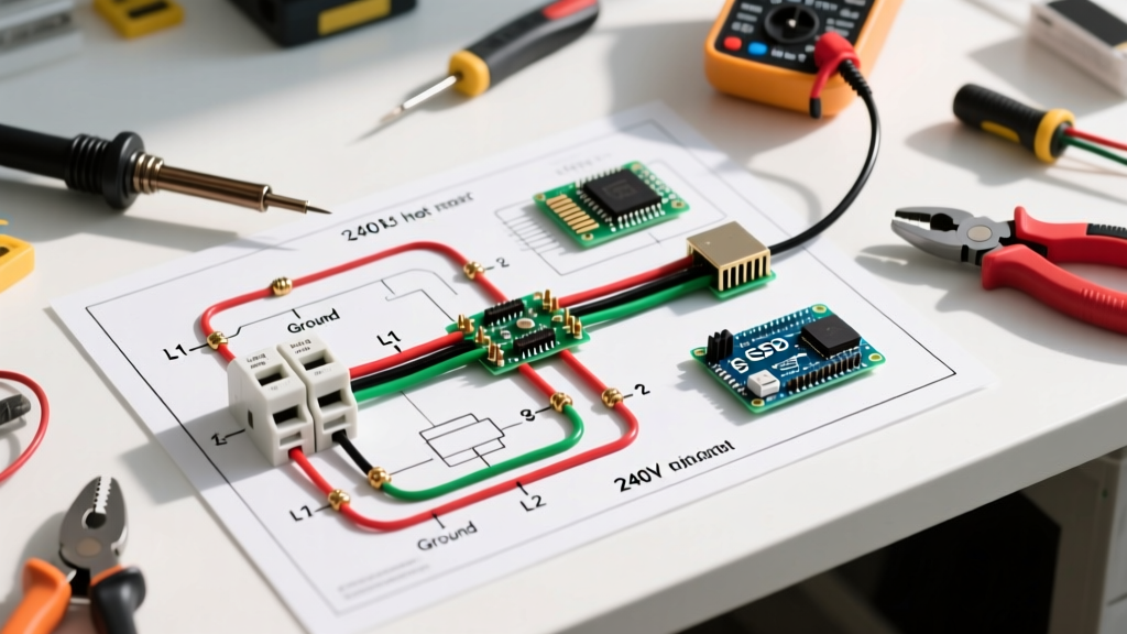
At its core, the schematic routes Line 1 (typically black) and Line 2 (typically white, re-identified with black tape) from a 2-pole breaker in your main service panel directly to the upper thermostat junction box. From there, power cascades to the upper heating element, the lower thermostat, and finally the lower heating element. The bare copper ground wire bonds the panel's ground bus bar to the metal chassis of the water heater, providing a critical fault-current path.
NEC Code Alert: According to the National Fire Protection Association (NFPA), NEC Article 422 governs the installation of fixed electric space heating and water heating equipment. Branch circuits must be sized at 125% of the continuous load if the heater operates continuously for 3 hours or more, though standard residential tank heaters are generally classified as non-continuous loads for branch circuit sizing.
Breaker Sizing & Wire Gauge Matrix
Selecting the correct breaker and wire gauge is dictated by the wattage of the heating elements. Most modern 40-to-50-gallon electric water heaters utilize dual 4500-watt elements. Because the thermostats are interlocked, only one element fires at a time, meaning the maximum continuous draw is based on a single 4500W element, not both simultaneously.
| Element Wattage | Voltage | Amperage (Calculated) | Min. Breaker Size | Min. Copper Wire Gauge |
|---|---|---|---|---|
| 3000W | 240V | 12.5A | 15A (2-Pole) | 14 AWG |
| 3800W | 240V | 15.8A | 20A (2-Pole) | 12 AWG |
| 4500W | 240V | 18.75A | 25A or 30A (2-Pole) | 10 AWG |
| 5500W | 240V | 22.9A | 30A (2-Pole) | 10 AWG |
Note: While a 25A breaker is technically permissible for a 4500W element under NEC 240.4(B) next-size-up rules, 30A double-pole breakers (like the Square D HOM230CP or Siemens Q230) are the industry standard due to widespread availability and compatibility with 10 AWG wire.
Panel Capacity & The 80% Bus Bar Rule
Before pulling wire, you must verify your electrical panel's capacity. A 30-amp, 240-volt water heater draws 7,200 watts (at 240V). If you are upgrading an older 100-amp service panel, adding a 30A double-pole breaker consumes 60 amps of total bus bar stab capacity (30A on Leg A, 30A on Leg B).
Calculating Panel Headroom
To ensure your panel isn't overloaded, perform a basic NEC Article 220 load calculation. Subtract the total amperage of all existing single-pole and double-pole breakers from your main breaker rating. If your main breaker is 200A, and your existing calculated load is 145A, you have 55A of headroom—plenty of room for the water heater. However, if you are relying on solar inverters or EV chargers sharing the same subpanel, you must account for those dynamic loads to prevent nuisance main-breaker trips.
Step-by-Step Wiring Procedure: Panel to Thermostat
Follow this precise sequence to ensure a safe, code-compliant installation. As of 2026, a 50-foot roll of Southwire 10/2 NM-B (Romex) averages around $65 to $80, while a standard Square D Homeline 30A 2-pole breaker costs approximately $18.
- De-energize the Panel: Turn off the main service disconnect. Verify zero voltage at the bus bars using a CAT III or CAT IV non-contact voltage tester and a digital multimeter.
- Install the Breaker: Snap the 30A 2-pole breaker into the panel. Ensure it seats fully on both bus bar stabs. Connect the black and white (re-identified) circuit wires to the breaker lugs. Critical: Torque the lug screws to the manufacturer's specification, typically 35 to 45 inch-pounds. Under-torqued lugs cause arcing and melted breaker housings over time.
- Route the NM-B Cable: Run the 10/2 NM-B cable from the panel to the water heater. Secure the cable with cable staples within 8 inches of the panel and every 4.5 feet along the run.
- Terminate at the Junction Box: At the water heater's top junction box, use a proper NM cable connector (clamp) to secure the wire. Do not simply push the Romex through the knockout hole, as the sharp metal edges will slice the insulation and cause a ground fault.
- Make the Connections: Connect the black wire to the L1 terminal and the re-identified white wire to the L2 terminal. Bond the bare copper ground wire to the green grounding screw on the junction box and the heater chassis. Use high-temperature rated wire nuts (like IDEAL 341) for any splices.
The Smart Heater Exception: When a Neutral is Required
The traditional electric hot water heater wiring schematic is evolving. Modern heat pump water heaters (HPWHs) and smart-enabled resistive heaters, such as the Rheem ProTerra series, incorporate Wi-Fi modules, digital displays, and 120V compressors.
According to the U.S. Department of Energy, heat pump water heaters are vastly more efficient but have different electrical requirements. Many of these units require a 120V dedicated 15-amp circuit for the control board and compressor, completely separate from the 240V backup heating elements. If your specific smart heater integrates both 240V elements and 120V controls into a single junction box, the schematic will mandate a 10/3 NM-B cable (Black, Red, White, Bare) and a 2-pole breaker with a pigtail to the neutral bus bar to provide the 120V return path. Always consult the manufacturer's specific wiring diagram on the inside of the access panel before pulling wire.
Troubleshooting Common Schematic Deviations
Even with a correct schematic, field conditions can introduce faults. Here is how to diagnose the most common issues:
- Breaker Trips Instantly Upon Reset: This indicates a dead short. The most common culprit is a burned-out heating element that has split its outer copper sheath, allowing water to contact the internal nichrome wire and ground out. Test elements for continuity to ground using a multimeter set to Ohms (Ω).
- Breaker Trips After 20-30 Minutes: This is a thermal overload issue. Check for loose connections at the breaker lugs or the thermostat terminals. Loose wires create high resistance, generating heat that transfers into the breaker's thermal trip mechanism.
- Water Heater 'Screams' or Pops: While not strictly an electrical schematic failure, sediment buildup at the bottom of the tank insulates the lower element, causing it to overheat and boil the surrounding water. This can eventually warp the element and alter its resistance, drawing abnormal amperage.
Frequently Asked Questions
Can I use a 40-amp breaker for a 4500-watt water heater?
No. NEC Article 240.4 requires conductors to be protected at their rated ampacity. 10 AWG copper wire is rated for 30 amps. Placing a 40-amp breaker on 10 AWG wire creates a severe fire hazard, as the wire will melt before the breaker trips during an overload.
Does the white wire need to be marked?
Yes. NEC Article 200.7(C) requires that any white or gray wire used as an ungrounded (hot) conductor must be permanently re-identified with black or red tape, or paint, at every termination point. Failing to do so can lead to lethal confusion for the next electrician working on the panel.