
Understanding the Wiring Diagram for GM Steering Column Systems
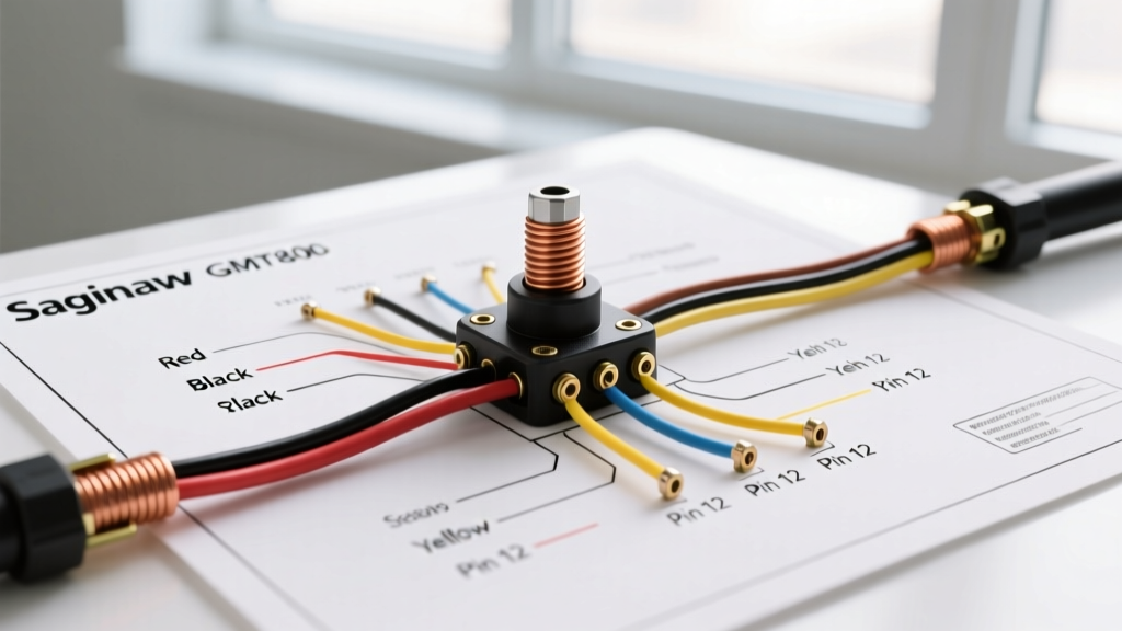
Whether you are performing a frame-off restoration on a 1972 Chevrolet C10 or diagnosing an electrical gremlin in a 2004 GMC Sierra, interpreting the wiring diagram for GM steering column assemblies is a critical skill. General Motors has utilized several steering column architectures over the decades, but the two most prominent in the DIY and restoration community are the classic Saginaw columns (1969–1980s) and the modern GMT800/GMT900 multi-function switch platforms. In 2026, with the rising cost of NOS (New Old Stock) GM parts, the ability to accurately trace, repair, and re-pin column connectors using aftermarket Packard Electric terminals is more valuable than ever.
This guide breaks down the exact pinouts, wire color codes, and common failure modes associated with GM steering columns, providing actionable data for your next electrical project.
Classic Saginaw Column: Turn Signal & Ignition Pinouts
The Saginaw steering column is legendary for its durability and widespread use across GM’s A-body (Chevelle, Cutlass), F-body (Camaro, Firebird), and C/K truck lines. The turn signal and hazard functions are routed through a multi-pin connector located near the base of the column. While early models used a 9-pin connector, later iterations transitioned to a 12-pin or 13-pin configuration to accommodate cruise control and intermittent wipers.
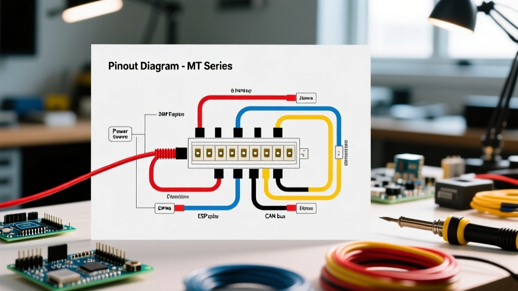
Below is the standard pinout reference for the ubiquitous Saginaw 9-pin turn signal switch connector. This is the primary junction where the chassis harness meets the column harness.
| Pin / Cavity | Standard GM Wire Color | Circuit Function | Wire Gauge (AWG) |
|---|---|---|---|
| 1 | Purple | Turn Signal Flasher Feed | 18 AWG |
| 2 | Light Blue | Right Front Turn Signal | 18 AWG |
| 3 | Yellow | Left Front Turn Signal | 18 AWG |
| 4 | Dark Green | Right Rear Turn Signal & Stop Lamp | 18 AWG |
| 5 | Brown | Left Rear Turn Signal & Stop Lamp | 18 AWG |
| 6 | White | Hazard Flasher Feed | 18 AWG |
| 7 | Black | Horn Relay Ground | 18 AWG |
| 8 | Dark Green | Right Rear Stop/Turn (Duplicate/Alt) | 18 AWG |
| 9 | Brown | Left Rear Stop/Turn (Duplicate/Alt) | 18 AWG |
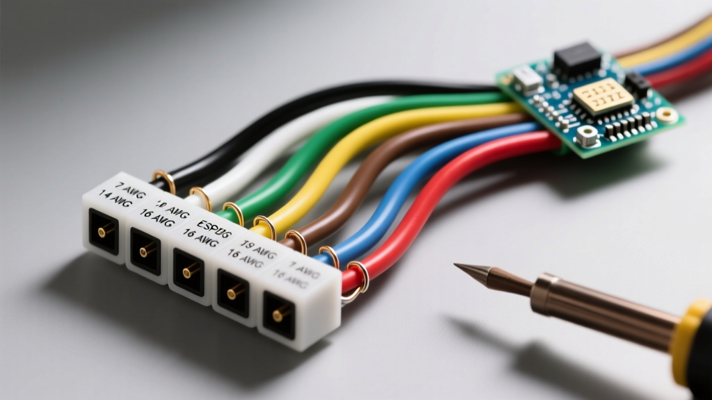
Expert Tip: When repairing these harnesses, do not use generic butt splices. Invest in a crimping tool designed for Packard 56-series terminals and use GXL or TXL cross-linked polyethylene wire. Standard PVC wire will become brittle under the dash over time due to heat cycling.
Modern GMT800 Multi-Function Switch (MFS) Architecture
Moving into the modern era, the GMT800 platform (1999–2006 Silverado, Sierra, Tahoe) consolidated the turn signals, wipers, cruise control, and headlight dimmer into a single Multi-Function Switch (MFS) mounted on the left side of the steering column. The wiring diagram for GM steering column setups of this era is vastly more complex, relying on multiplexed signals and the Body Control Module (BCM).
Key GMT800 MFS Circuits and Connector C201
The MFS connects to the main chassis harness via the C201 bulkhead connector (a massive 80+ pin block located under the driver's side dash). Troubleshooting requires isolating the column side from the chassis side at C201.
- Headlamp Dimmer Feed: Tan (14 AWG) - Carries high current from the headlamp switch. Prone to voltage drop if the MFS internal contacts degrade.
- Wiper Motor Control: Gray (Low), Dark Green (High), and Purple (Washer). These are direct 12V feeds, not BCM multiplexed signals, meaning you can test them directly with a Power Probe.
- Cruise Control: Uses a dedicated 4-pin connector on the column. The Gray wire is the cruise ON/OFF signal to the PCM, while the Purple/White handles the Set/Coast functions.
Step-by-Step Troubleshooting of Common Column Failures
Electrical issues in GM steering columns rarely stem from broken wires inside the column tube; instead, they are almost always caused by switch degradation, connector melting, or clock spring failure. Here is how to diagnose the most frequent culprits.
Failure Mode 1: The Saginaw Hazard Switch Melt
The Symptom: Turn signals work, but when you engage the hazard flashers, the lights illuminate solidly and do not flash, or you smell melting plastic under the dash.
The Root Cause: The factory hazard switch routes the current for all four corner bulbs (and sometimes the side markers) through a single internal copper contact and the standard thermal flasher can. This draws upwards of 8 to 10 amps through 18 AWG wire and tiny switch contacts, generating massive heat.
The Fix: Bypass the factory hazard routing. Install an external heavy-duty solid-state LED flasher relay and wire a separate 14 AWG feed directly from the fuse box to the hazard switch input, relieving the internal column contacts of the high current load.
Failure Mode 2: GMT800 Clock Spring (SIR Coil) Degradation
The Symptom: The SIR (Supplemental Inflatable Restraint) airbag light illuminates on the dash, accompanied by a loss of horn function and steering wheel audio controls. Code B0051 or B0024 is stored in the SDM (Sensing and Diagnostic Module).
The Root Cause: The clock spring is a coiled ribbon cable inside the column that maintains electrical continuity while the wheel turns. Over 20+ years, the ribbon fatigues and snaps.
Testing Protocol: According to NHTSA guidelines on airbag safety, you must disconnect the battery and wait at least 15 minutes before working near SIR components. Using a high-impedance digital multimeter (following Fluke's multimeter testing protocols), measure the resistance across the clock spring airbag pins. A healthy GMT800 clock spring will read between 1.8 and 2.2 ohms. An open circuit (OL) confirms a broken ribbon.
CRITICAL SAFETY WARNING: NEVER use a standard multimeter's continuity beep function or apply external voltage to the airbag squib (initiator) pins. The minimal current from some cheaper multimeters or test lights is enough to inadvertently deploy the airbag, causing severe injury or death.
Essential Tools for GM Column Wiring in 2026
To properly service these systems, generic tools will lead to damaged terminals and misdiagnoses. Equip your bench with the following:
- Terminal Removal Tools: The Lisle 45600 or equivalent GM-specific pin extraction set is mandatory for removing Packard 56 and Weather-Pack terminals without breaking the locking tangs.
- Digital Multimeter: A Fluke 117 or 87V (retailing around $250–$350 in 2026) provides the necessary low-impedance (LoZ) mode to detect ghost voltages in GM multiplexed BCM circuits.
- Wire Crimpers: The Titan 11477 or Delphi (Aptiv) specific crimpers ensure a gas-tight crimp on 18 AWG to 14 AWG GXL wire, preventing corrosion under the dash.
Frequently Asked Questions (FAQ)
Can I use a standard GM column wiring diagram for an aftermarket steering column?
Yes, but with caveats. Aftermarket columns (like those from ididit or Flaming River) use the exact same Saginaw-based turn signal switches internally. Therefore, the wiring diagram for GM steering column color codes applies perfectly. However, the physical connector on the aftermarket harness is often a modern Weather-Pack or Deutsch connector rather than the vintage Packard 56 block, requiring you to re-pin the chassis side.
Why do my turn signals flash rapidly on my classic GM truck?
Rapid flashing indicates high resistance in the circuit, usually a burnt-out bulb or a corroded ground at the tail light housing. However, if all bulbs are functional, check the Purple wire feed at the column connector. A loose Packard terminal here will cause a voltage drop, tricking the thermal flasher into cycling too quickly.
Where can I find the official SAE standards for these wire colors?
GM adheres to internal wiring standards that largely align with SAE technical standards for automotive wire insulation and color coding. While SAE dictates the testing parameters for the wire (like GXL/TXL temperature ratings), GM's specific color-coding matrix is proprietary to their service manuals, though universally documented in aftermarket GM chassis repair guides.