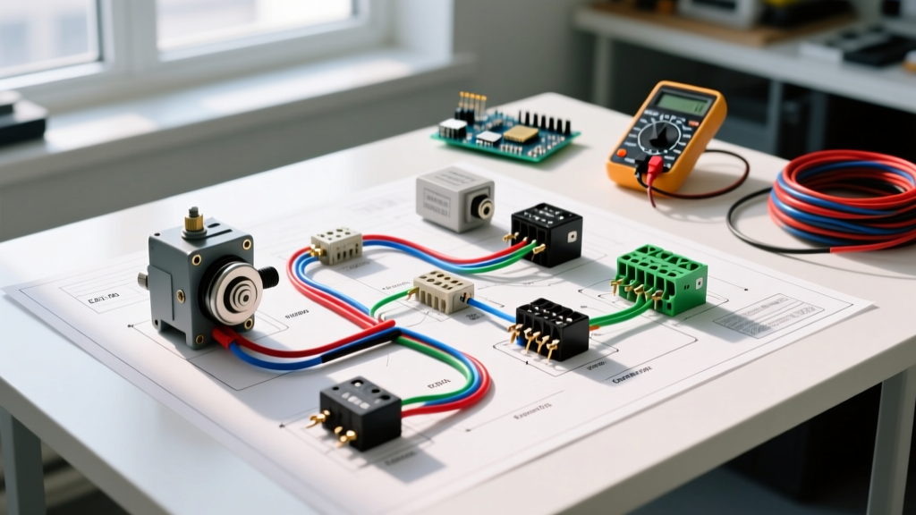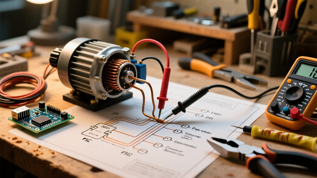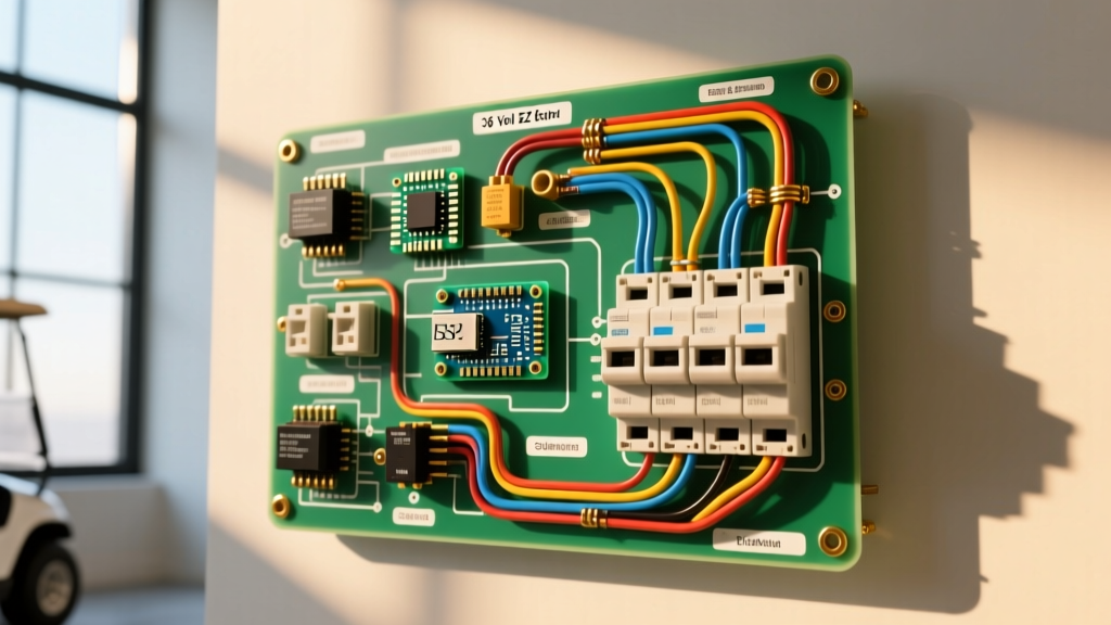

Decoding the 36V EZ-GO TXT Electrical Architecture
The 36-volt EZ-GO TXT platform—spanning the Series, DCS (Drive Control System), and PDS (Precision Drive System) models produced from 1994 through 2013—remains one of the most widely serviced electric vehicles in fleet and residential use today. When interpreting a wiring diagram for 36 volt EZ GO golf cart systems, technicians and DIYers often focus heavily on the battery series connections while neglecting the critical DC breaker panel and solenoid gating circuits. As of 2026, with the mass adoption of 36V LiFePO4 (Lithium Iron Phosphate) drop-in battery packs, understanding the original equipment manufacturer (OEM) panel architecture is more crucial than ever to prevent BMS (Battery Management System) faults and thermal runaway.
Unlike standard AC household panels, a golf cart DC panel must handle massive inrush currents and continuous high-amperage loads without suffering from voltage drop or thermal fatigue. This guide provides a deep-dive into the breaker sizing, high-current routing, and low-current control integration required to safely wire and maintain a 36V EZ-GO electrical system.
Panel & Breaker Component Specifications
The main electrical panel of a 36V EZ-GO TXT is not a single enclosed box like a residential breaker panel; rather, it is a distributed network of high-current fuses, magnetic DC circuit breakers, and heavy-duty contactors (solenoids). Selecting the correct amperage and wire gauge is non-negotiable for fire safety and performance.
| Component | OEM / Recommended Spec | Wire Gauge | Est. Cost (2026) | Function & Placement |
|---|---|---|---|---|
| Main DC Breaker | 400A Magnetic (e.g., Blue Sea / Bussmann) | 2 AWG | $45 - $75 | Primary short-circuit protection; placed on the main positive lead directly off the battery pack. |
| High-Current Solenoid | 36V 4-Terminal (Albright SW200 or OEM equivalent) | 2 AWG to 4 AWG | $40 - $90 | Acts as the primary electronic relay connecting battery power to the motor controller. |
| Charge Receptacle | 3-Pin D-Plug (IPI or Powerwise) | 6 AWG | $18 - $30 | Routes charger DC directly to the battery pack, bypassing the main controller. |
| Controller / Motor Cables | High-Strand Welding Cable | 2 AWG | $3.50 / ft | Connects the controller to the series/sepex motor. Must be highly flexible. |
| Control Circuit Wiring | 16 AWG THHN / Automotive GXL | 16 AWG | $0.40 / ft | Routes 36V through key switch, F/R microswitches, and throttle to trigger the solenoid. |
High-Current Routing: Battery to Motor
The high-current side of the wiring diagram dictates the physical movement of amperage from the battery bank to the drive motor. In a 36V system, peak current can exceed 350 amps during steep hill climbs or heavy towing. According to Blue Sea Systems' DC circuit protection guidelines, DC breakers must be sized to handle the continuous load of the controller while tripping instantaneously under a dead short.
Step-by-Step Main Panel Routing
- Battery Interconnects: Wire six 6V lead-acid batteries (or three 12V lithium equivalents) in series using 2 AWG cables. Torque all battery terminal lugs to exactly 120 in-lbs. Under-torquing causes arcing; over-torquing strips the soft lead posts.
- Main Positive Routing: Route the main positive cable from the first battery's positive post directly to the input terminal of the 400A DC main breaker. Do not route this through the solenoid first; the breaker must protect the entire downstream system.
- Breaker to Solenoid: From the breaker's output terminal, run a 2 AWG cable to the large input stud (Terminal A) on the 36V solenoid.
- Solenoid to Controller: Connect the large output stud (Terminal B) on the solenoid to the B+ (Battery Positive) terminal on the motor controller.
- Controller to Motor: Wire the controller's U, V, and W terminals (for AC conversions) or A1, A2, S1, S2 terminals (for DC Sepex/Series motors) using 2 AWG high-strand cable. Ensure phase sequence is correct to prevent reverse rotation on startup.
- Main Negative Return: The main negative from the last battery in the series must route directly to the controller's B- (Battery Negative) terminal, completing the high-current circuit.
Low-Current Control Circuit Integration
The control circuit is the 'brain' of the panel. It uses a fraction of an amp to signal the solenoid to close the high-current gates. The wiring diagram for this section varies significantly depending on whether your TXT is a Series, DCS, or PDS model.
The Solenoid Activation Sequence
For the solenoid to engage, 36 volts must reach both small terminals (S1 and S2).
- Terminal S1 (Constant Hot): Receives 36V directly from the main positive line (usually tapped at the breaker input or solenoid large terminal) via a 16 AWG wire routed through the key switch and the Forward/Reverse microswitch assembly.
- Terminal S2 (Switched Ground/Hot): Receives the activation signal only when the throttle is pressed. On PDS models, the controller itself provides this signal via a solid-state internal ground switch. On older Series models, S2 routes through the V-Glide potentiometer box and throttle microswitches.
Expert Troubleshooting Tip: If your solenoid clicks but the cart does not move, the control circuit is functioning perfectly. The failure lies in the high-current side (burnt solenoid contacts, blown controller MOSFETs, or a tripped main breaker). If the solenoid does not click, use a multimeter to test for 36V at S1 and S2 while the key is on and the pedal is depressed.
2026 Perspective: Lithium Drop-In Upgrades and BMS Integration
As of 2026, over 60% of aging 36V EZ-GO TXT fleets are being retrofitted with 36V LiFePO4 drop-in batteries. This fundamentally alters the charging panel and breaker requirements. Lithium batteries feature an internal BMS that will instantly sever the circuit if it detects a voltage spike or over-current event.
When wiring a lithium pack, the stock 36V Lester Summit or Delta-Q chargers are often incompatible without a CAN-bus communication adapter. Furthermore, the charge receptacle wiring must be upgraded. The OEM 6 AWG wires leading from the 3-pin D-plug to the battery pack should be inspected for heat degradation. Because lithium packs accept a higher continuous charge current (often 0.5C compared to lead-acid's 0.1C), upgrading the charge receptacle wiring to 4 AWG is highly recommended to prevent voltage drop, which can trick the BMS into prematurely terminating the charge cycle. For comprehensive data on charging profiles and battery health, refer to the Battery University guidelines on charging methodologies.
Diagnostic Matrix: Voltage Drops and Breaker Trips
Electrical faults in 36V golf carts rarely present as simple 'broken wires.' They manifest as thermal fatigue, voltage drops, and nuisance trips. Use the following diagnostic matrix to isolate panel and breaker faults.
| Symptom | Probable Cause | Diagnostic Action & Measurement |
|---|---|---|
| Main 400A breaker trips instantly upon pressing the pedal. | Dead short in the motor or controller (blown MOSFETs). | Disconnect motor leads from the controller. Test motor windings for continuity to ground. Replace controller if MOSFETs are shorted. |
| Breaker trips after 10-15 minutes of continuous driving. | Thermal fatigue in breaker or undersized amperage rating. | Measure voltage drop across the breaker terminals under load. A drop >0.15V indicates internal corrosion or failing contacts. Replace breaker. |
| Solenoid clicks rapidly (machine-gun sound) under load. | Voltage drop in the control circuit or failing battery cell. | Measure voltage at S1 and S2 while the pedal is held down. If voltage drops below 28V, the solenoid drops out. Check 16 AWG control wires for corrosion. |
| Cart runs sluggishly; batteries drain excessively fast. | High resistance in battery interconnects or main panel lugs. | Perform a voltage drop test across every cable connection under load. Any single cable showing >0.05V drop must be cleaned or replaced. |
Safety Standards and Final Panel Assembly
While golf carts are not strictly governed by the National Electrical Code (NEC) for internal DC wiring, adhering to NFPA 70 (NEC) Article 480 standards for storage battery installations ensures maximum safety. This includes maintaining proper clearance around battery terminals, using insulated terminal boots on all 2 AWG lugs, and ensuring the main breaker is easily accessible and clearly labeled.
When reassembling the panel and battery compartment, always apply a thin layer of dielectric grease or anti-corrosion spray to the battery posts and lug interfaces. The 36V EZ-GO TXT is a robust platform, but its longevity is entirely dependent on the integrity of its DC breaker panel and the precision of its wiring connections. By following this architectural guide, you ensure reliable, safe, and high-performance operation for both legacy lead-acid and modern lithium configurations.