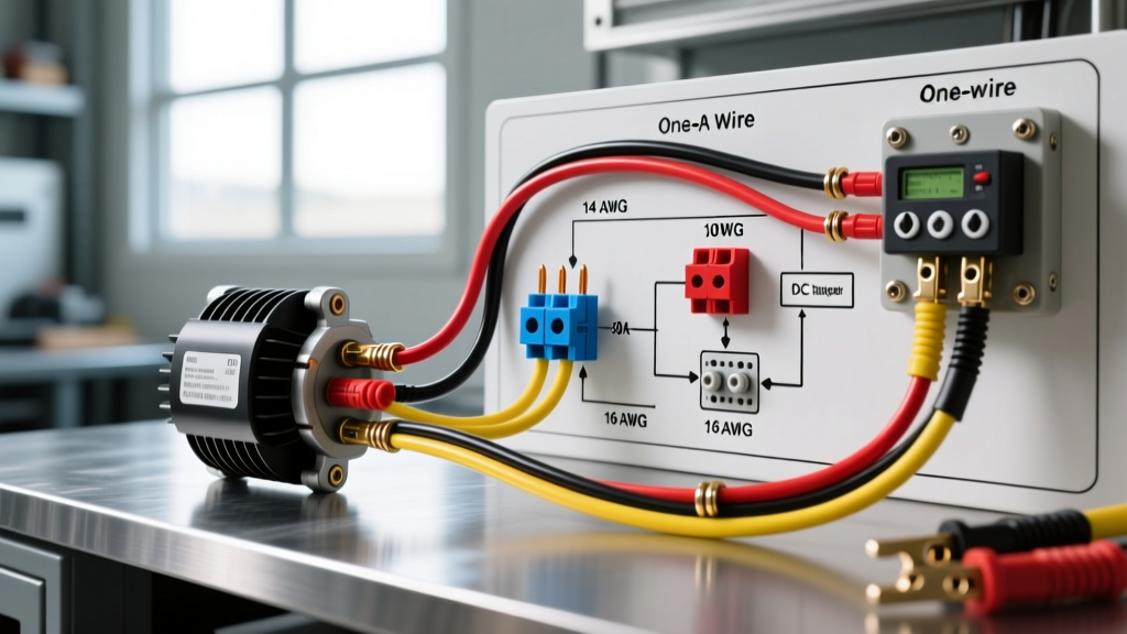

The Complete Guide to Electric Fan Wiring Diagrams
Electric fan wiring encompasses a broad spectrum of applications, from simple single-phase 120V residential ceiling fans to complex multi-tap Permanent Split Capacitor (PSC) and Electronically Commutated Motors (ECM) used in industrial ventilation. Whether you are retrofitting a Hunter 59244 ceiling fan, installing a Panasonic WhisperCeiling exhaust unit, or wiring a 3-speed Dayton inline duct fan, understanding the underlying electrical schematics is critical for safety and optimal performance.
In 2026, the National Electrical Code (NEC) continues to enforce strict guidelines on motor overcurrent protection and junction box ratings. According to the National Fire Protection Association (NFPA), improper fan wiring remains a leading cause of residential electrical fires, often stemming from undersized wire gauges or missing equipment grounding conductors. This guide provides actionable, diagram-based explanations for the three most common electric fan wiring scenarios.
1. Standard Ceiling Fan with Integrated Light Kit
Most modern residential ceiling fans, such as the popular Minka-Aire and Hunter models, utilize a dual-circuit wiring configuration. This allows the fan motor and the light kit to be controlled independently from a wall-mounted dual switch or a remote control receiver.
Wiring Color Code & Connections
- Black (Ceiling) to Black (Fan): Provides the primary 'hot' power to the fan motor.
- Red (Ceiling) to Blue (Fan): Provides the secondary 'hot' power specifically for the light kit.
- White (Ceiling) to White (Fan): The neutral return path, shared by both the motor and the light.
- Bare/Green (Ceiling) to Green (Fan): The equipment grounding conductor.
NEC Code Alert: Under NEC Article 410.16, ceiling fans must be supported by an outlet box specifically listed and rated for ceiling fan support (typically marked 'Acceptable for Fan Support'). Standard drywall-rated junction boxes will fail under the dynamic torque of a 35-pound fan spinning at 180 RPM.
If your wall only has a single hot wire (no red wire), you must wire the black and blue fan wires together to the single black ceiling wire. This setup powers both the fan and light simultaneously, requiring you to use the pull chains or an integrated remote receiver module to control them independently.
2. Bathroom Exhaust Fan with Humidity Sensor
Upgrading to a smart or humidity-sensing exhaust fan, like the Panasonic FV-0511VQ1 WhisperCeiling (retailing around $185 in 2026), requires careful attention to the sensor's power requirements. Unlike standard exhaust fans that simply break the hot leg, sensor-equipped fans often require a constant 120V supply to power the internal logic board, even when the fan is off.
Diagram Explanation: Sensor-Equipped Exhaust Fan
- Line (Hot) Input: Connect the always-hot black wire from the breaker panel to the fan's black 'Line' wire. This keeps the humidity sensor energized 24/7.
- Switched Hot (Optional): If you want manual override via a wall switch, the switch leg connects to the fan's designated 'Switch' wire (often red or blue depending on the manufacturer).
- Neutral: Connect the white wire from the panel to the fan's white neutral wire. Never use the ground wire as a neutral return path; this will trip modern AFCI/GFCI breakers immediately.
- Ground: Bond the bare copper ground to the fan's metal chassis and the green ground wire.
For optimal moisture mitigation, the ENERGY STAR ventilation guidelines recommend setting the humidity threshold to 60% and ensuring the duct run to the exterior uses rigid metal or smooth-wall PVC, avoiding ribbed flex duct which restricts CFM airflow and strains the motor.
3. 3-Speed PSC (Permanent Split Capacitor) Motor Wiring
Industrial box fans, inline duct boosters, and workshop air circulators frequently use PSC motors. These motors rely on a run capacitor (typically rated between 1.5 µF and 5.0 µF at 370VAC) to create a phase shift in the auxiliary winding, generating the starting torque.
Understanding the Speed Taps
A standard 3-speed PSC motor will have four primary wires exiting the stator housing: Line (Hot), Neutral, and two or three speed tap wires (High, Medium, Low). The speed is controlled by inserting varying amounts of inductive reactance (extra winding coils) into the circuit.
- High Speed: Power is applied directly to the main run winding. Maximum current, maximum RPM.
- Medium/Low Speed: Power is routed through additional auxiliary winding coils, increasing impedance, dropping the voltage across the main winding, and reducing RPM.
Wiring the Capacitor: The capacitor is wired in series with the start/auxiliary winding. It is non-polarized, meaning the two capacitor leads can be connected to the designated auxiliary wires in either direction. If the capacitor fails (bulges or reads open on a multimeter), the motor will hum but fail to start. You can temporarily push the blade with a wooden dowel to verify a bad capacitor; if it starts running when pushed, replace the capacitor immediately.
Wire Gauge and Breaker Sizing Matrix
Selecting the correct wire gauge and overcurrent protection device (OCPD) is non-negotiable. The OSHA Wiring Methods Standards and NEC Article 430 dictate that motor circuits must account for locked-rotor amperage (LRA) and continuous load multipliers.
| Fan Type / Application | Typical Amperage | Min. Wire Gauge (Copper) | Breaker Size | NEC Reference |
|---|---|---|---|---|
| Standard Ceiling Fan (w/ Light) | 0.5A - 1.5A | 14 AWG | 15A | Art. 210 / 410 |
| Bathroom Exhaust (110 CFM) | 0.2A - 0.4A | 14 AWG | 15A | Art. 210 |
| Whole House Fan (1/3 HP) | 4.0A - 6.0A | 12 AWG | 20A | Art. 430 |
| Industrial Inline Duct (1/2 HP) | 7.0A - 9.5A | 12 AWG | 20A | Art. 430.52 |
| Heavy Duty Pedestal (1 HP) | 12.0A - 15.0A | 10 AWG | 30A | Art. 430.52 |
Troubleshooting Common Electric Fan Wiring Failures
Failure Mode 1: Motor Hums but Will Not Spin
Diagnosis: This is almost always a failed run capacitor or a seized bearing. Disconnect power, safely discharge the capacitor using a 20k-ohm 5-watt resistor, and test it with a multimeter equipped with a capacitance setting. A 5.0 µF capacitor should read within 6% of its rating (4.7 to 5.3 µF). If it reads 'OL' (open) or near zero, replace it with an exact match for both MFD and voltage rating (e.g., replacing a 370VAC with a 440VAC is acceptable, but never vice versa).
Failure Mode 2: Fan Spins in the Wrong Direction
Diagnosis: In single-phase AC motors, rotation direction is determined by the phase relationship between the main and auxiliary windings. If an exhaust fan is blowing air inward instead of outward, or a ceiling fan is pushing air up instead of down (and the physical switch is set correctly), the start winding leads have likely been reversed. Swap the two wires connecting the auxiliary winding to the power source and capacitor to reverse the magnetic field rotation.
Failure Mode 3: Tripping AFCI/GFCI Breakers Immediately
Diagnosis: Older fans with degraded internal insulation or moisture-damaged exhaust fans can leak milliamps of current to the ground. Modern AFCI/GFCI breakers trip at a 5mA threshold. Check for pinched wires inside the junction box, ensure the neutral and ground are not bonded downstream of the main panel, and verify the motor windings for a short to the chassis using a megohmmeter (Megger) if available.
Final Safety Protocols
Before terminating any electric fan wiring, always verify the circuit is de-energized using a non-contact voltage tester (NCVT) and a digital multimeter (DMM) testing line-to-neutral and line-to-ground. Torque all wire nuts and terminal block screws to the manufacturer's specifications; loose connections on motor circuits generate immense heat due to arcing, leading to melted insulation and catastrophic failure. By adhering to these schematic principles and NEC guidelines, your fan installations will remain safe, efficient, and reliable for years to come.