
Decoding the Electric Fan Wiring Diagram: Motor Types and Topologies
Wiring an electric fan is rarely a simple 'connect hot to hot' scenario. Whether you are retrofitting a residential ceiling fan, replacing an HVAC blower motor, or troubleshooting an industrial exhaust unit, understanding the underlying motor topology is mandatory. In 2026, while Electronically Commuted Motors (ECMs) dominate new high-efficiency builds, Permanent Split Capacitor (PSC) and Shaded Pole motors remain the backbone of millions of existing systems and aftermarket replacements. This comprehensive motor wiring tutorial breaks down the exact electric fan wiring diagrams, terminal mappings, and failure modes for these workhorse motors.
Permanent Split Capacitor (PSC) Motors
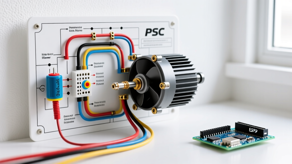
PSC motors are the industry standard for ceiling fans, attic exhaust fans, and HVAC blowers (typically ranging from 1/4 HP to 1 HP). They utilize a run capacitor to create a phase shift between the start and run windings, generating the rotating magnetic field required for startup and continuous torque. Unlike capacitor-start motors, the capacitor in a PSC motor remains in the circuit during operation, which is why correct microfarad (MFD) rating selection is critical.
Shaded Pole Motors
Found in low-torque applications like bathroom exhaust fans (e.g., Broan 678 series) and small desk fans, shaded pole motors lack a capacitor. Instead, they use a copper shading coil wrapped around a portion of the stator pole to create the phase shift. Wiring is straightforward—typically just two leads (Line and Neutral)—but thermal management is their primary vulnerability.
NEC Compliance: Wire Gauge and Overcurrent Protection
Before touching a single terminal, you must size your conductors according to the motor's Full Load Amps (FLA). The NFPA 70 (National Electrical Code) Article 430 dictates that motor branch circuits must be sized at 125% of the motor's FLA to prevent nuisance tripping during startup inrush currents.
| Motor FLA Rating | Min. Copper Wire Gauge (THHN) | Max Breaker Size (Inverse Time) | Max Run Length (for <3% Voltage Drop at 120V) |
|---|---|---|---|
| 1.0A - 2.5A | 14 AWG | 15 Amp | 55 Feet |
| 2.6A - 5.0A | 12 AWG | 20 Amp | 70 Feet |
| 5.1A - 8.0A | 10 AWG | 30 Amp | 65 Feet |
| 8.1A - 12.0A | 8 AWG | 40 Amp | 80 Feet |
Expert Warning: Never use a standard lighting dimmer switch to control a PSC fan motor. Dimmers chop the AC sine wave, which causes severe harmonic distortion, rapid motor overheating, and eventual winding insulation failure. Always use a rated fan speed controller (e.g., Lutron Skylark SFS-5E) designed for inductive motor loads.
Step-by-Step Electric Fan Wiring Diagram: 3-Speed PSC HVAC Blower
Let's examine a real-world scenario: wiring a replacement 1/2 HP, 1050 RPM PSC blower motor (such as the Fasco A684 or Century H32V1). These motors feature multiple speed taps and require a dual-run or specific single-run capacitor.
Terminal Identification and Mapping
- White (Common): The main return path for all windings. Connects to the neutral side of the contactor.
- Black (High Speed): Connects to the hot side of the contactor for maximum CFM output.
- Blue (Medium Speed) / Red (Low Speed): Alternative speed taps. Crucial: Unused speed taps must be insulated and tucked away; they will carry induced voltage while the motor runs.
- Yellow & Brown: Dedicated capacitor terminals.
The Wiring Sequence
- Power Isolation: Engage Lockout/Tagout (LOTO) on the main disconnect. Verify zero voltage using a CAT III multimeter at the contactor terminals.
- Capacitor Integration: Connect the Yellow and Brown motor leads to the 'F' (Fan) and 'C' (Common) terminals on the dual-run capacitor (e.g., Genteq 97F9838, typically 5 MFD / 370VAC for this motor size). Polarity does not matter on AC run capacitors.
- Contactor Wiring: Route the 240V Line 1 to the motor's White (Common) wire. Route Line 2 through the contactor relay to the Black (High) wire.
- Grounding: Attach the green chassis ground screw to the equipment grounding conductor (EGC). Never rely on the mounting bracket for a ground path.
Critical Failure Modes and Edge Cases
Understanding how an electric fan wiring diagram fails is just as important as knowing how to wire it correctly. Here are the most common field mistakes we diagnose:
1. Floating Speed Taps (The 'Ghost Voltage' Burnout)
If you wire the hot lead to the Medium (Blue) tap but forget to insulate the High (Black) tap, the rotating magnetic field will induce a high-voltage back-EMF into the unused winding. Over 48 to 72 hours, this induced voltage breaks down the enamel insulation on the copper windings, resulting in an inter-turn short and a dead motor.
2. Incorrect Capacitor MFD Sizing
Replacing a 5 MFD capacitor with a 10 MFD unit will not 'give the fan more power.' Instead, it over-excites the start winding, increasing amperage draw by up to 40% and tripping the motor's internal thermal overload protector within minutes. Always match the MFD rating exactly (usually +/- 6% tolerance).
3. Shaded Pole Thermal Fuse Blowing
In bathroom exhaust fans, lint accumulation acts as an insulator. The motor's internal thermal fuse (typically rated at 115°C / 239°F) will permanently open. While replacing the $45 motor assembly is the standard fix, advanced DIYers can crimp a replacement SEFUSE SF226E thermal cutoff ($2.50) directly onto the stator winding, provided they use high-temp fiberglass sleeving and avoid soldering (which transfers heat and blows the new fuse during installation).
Advanced Troubleshooting: Multimeter Diagnostics
Before replacing a suspected dead motor, perform a bench test. According to Fluke Corporation's Guide on Testing Capacitors, a swollen or leaking capacitor is an obvious failure, but internal winding degradation requires a multimeter set to Ohms (Ω).
Winding Resistance Testing Protocol
Disconnect all power and isolate the motor leads. Measure resistance between the Common terminal and the speed taps. For a standard 1/2 HP PSC motor, you should see a progressive resistance ladder:
- Common to High (Black): ~2.5 Ω (Lowest resistance, thickest wire)
- Common to Medium (Blue): ~3.8 Ω
- Common to Low (Red): ~6.1 Ω (Highest resistance, thinnest wire)
If your multimeter reads 'OL' (Open Loop) between Common and any tap, the internal thermal overload has tripped or the winding is severed. If it reads 0.0 Ω, you have a dead short. In either case, the motor must be replaced.
Frequently Asked Questions (FAQ)
Can I wire a PSC fan motor without the capacitor?
No. Without the capacitor to create the phase shift, the motor will simply hum, draw locked-rotor amperage (LRA), and trip its internal thermal overload within 10 to 15 seconds. You can manually spin the shaft with a non-conductive stick to start it, but it will run with severely reduced torque and overheat rapidly.
Why does my ceiling fan run backward after rewiring?
Single-phase AC motors do not have a 'polarity' that dictates direction. If a replacement motor spins backward, the manufacturer's internal winding layout is reversed compared to your old unit. To fix this, you must physically swap the start and run winding connections at the motor's internal terminal block, or simply flip the blade pitch if the motor housing allows for reverse mounting.
Do I need to upgrade my wire gauge for a high-CFM industrial exhaust fan?
Yes. Industrial shutter-mount exhaust fans (like the Dayton 4WT45) often pull 8 to 12 amps on a 120V circuit. You must upgrade from standard 14 AWG residential wiring to 10 AWG or 8 AWG copper, and install a dedicated 30A or 40A breaker to comply with NEC Article 430 motor circuit requirements.