
The Legacy and Electrical Complexity of the John Deere 318
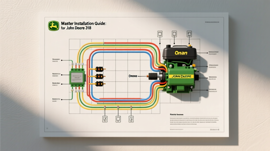
Produced between 1984 and 1992, the John Deere 318 remains one of the most highly sought-after lawn and garden tractors in the collector and heavy-user market. Unlike simpler mechanical tractors of its era, the 318 features a remarkably complex electrical system designed to support the Onan B43E (18HP) or P218 (20HP) twin-cylinder engines, an electric PTO clutch, a sophisticated charging system, and multiple safety interlocks. As we navigate the restoration landscape in 2026, finding a pristine OEM harness is nearly impossible. Consequently, fabricating a custom loom using a factory-accurate wiring diagram for John Deere 318 tractors is the standard approach for serious restorers.
This installation planning guide moves beyond basic schematics. It provides the actionable specifications, wire gauge requirements, and edge-case troubleshooting data necessary to execute a flawless, fire-safe rewire of your JD 318.
Phase 1: Pre-Installation Audit and Material Selection
Before cutting a single wire, you must audit the existing system and source the correct materials. The original PVC-insulated wires used in the 1980s become brittle and crack when exposed to engine heat and vibration.
Required Materials and Tooling
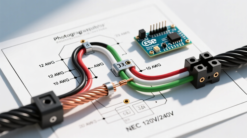
- Wire Type: Use SAE J1128 compliant GXL or TXL cross-linked polyethylene wire. These offer superior heat resistance (up to 125°C) and a thinner insulation wall, allowing more wires to fit through the firewall bulkhead. Refer to the SAE J1128 Standard for exact automotive wire specifications.
- Terminals: Abandon standard vinyl-insulated crimps. Use adhesive-lined heat shrink terminals and a ratcheting crimp tool to ensure gas-tight connections that resist moisture ingress.
- Testing Equipment: A digital multimeter (DMM) capable of measuring down to 0.1 ohms, and an inductive clamp meter to measure PTO clutch amperage draw under load.
Phase 2: Decoding the Wiring Diagram for John Deere 318
The factory schematic can be overwhelming due to the intersection of the ignition, charging, and safety circuits. Below is a structured breakdown of the primary circuits, mapped to modern wire color standards and gauge requirements.
Circuit Breakdown and Wire Gauge Matrix
| Circuit Function | Wire Color (Std) | Gauge (AWG) | Fuse / Protection | Notes & Routing |
|---|---|---|---|---|
| Battery to Starter Solenoid | Red | 6 AWG | Main Fusible Link (60A) | Keep as short as possible; route away from exhaust. |
| Stator to Rectifier/Regulator | Yellow (x2) | 14 AWG | None (AC Output) | Onan B43E/P218 outputs ~30VAC. Do not fuse AC side. |
| Regulator to Battery (Charge) | Red | 10 AWG | 20A Inline Fuse | Must have a dedicated, clean ground to the engine block. |
| Electric PTO Clutch | Blue | 12 AWG | 10A Fuse | Draws ~2.5A. Must be wired through a 30A automotive relay. |
| Ignition & Accessories | White/Red | 14 AWG | 15A Fuse | Feeds the ignition switch, hour meter, and dash lights. |
| Safety Interlocks (Seat/Brake) | Gray/Black | 16 AWG | None (Low Current) | Controls the ignition ground-kill circuit and starter solenoid. |
Phase 3: The Bulkhead Connector Bottleneck
The most notorious failure point on the JD 318 is the multi-pin bulkhead connector that bridges the dashboard harness and the engine compartment harness. Over decades, the original AMP connectors suffer from terminal fretting corrosion, leading to voltage drops that mimic a failing voltage regulator or a weak battery.
Modernization Strategy
Instead of trying to source an obsolete OEM bulkhead plug, modern installation planning dictates eliminating it entirely or replacing it with sealed connectors.
- Direct Solder & Seal: For show-quality restorations where the dash must be removable, replace the single bulkhead block with three separate Deutsch DT series sealed connectors (e.g., a 4-pin, a 6-pin, and a 2-pin). This separates high-current charging wires from low-current signal wires, preventing cross-talk and heat transfer.
- Dielectric Grease: Apply a liberal amount of Nyogel 760G or standard dielectric grease to all connector pins to prevent galvanic corrosion between dissimilar metals.
Phase 4: Onan Engine Harness and PTO Clutch Routing
The Onan B43E and P218 engines require specific attention to the charging stator and the electric PTO clutch. Miswiring here is the leading cause of electrical fires in restored 318s.
Stator and Regulator Grounding
The Onan stator generates alternating current (AC) which is rectified to direct current (DC) by the voltage regulator. The regulator relies on the engine block for its ground path. Because the 318 engine sits on rubber vibration isolators, the ground path through the chassis is often insufficient.
Critical Expert Warning: Never rely solely on the engine mounting bolts for the regulator ground. Always run a dedicated 12 AWG braided ground strap from the voltage regulator mounting bracket directly to the battery negative terminal or the main chassis ground bus. A poor ground will cause the regulator to overheat and fail, potentially sending 30+ VDC into your 12V system and destroying the ignition coil and dash lights.
Electric PTO Clutch Relay Integration
The factory wiring diagram for John Deere 318 models often routes PTO power directly through the dash switch. The original Warner electric PTO clutch draws between 2.5 and 3.0 amps continuously. Over time, the dash switch contacts degrade, creating resistance, heat, and eventual melting of the switch housing.
The Fix: Install a standard 12V 30A Bosch-style automotive relay in the engine bay.
- Terminal 30: Connect to the battery positive via a 10A fuse.
- Terminal 87: Connect to the PTO clutch positive wire.
- Terminal 86: Connect to the PTO dash switch output (trigger wire).
- Terminal 85: Connect to a clean chassis ground.
This ensures the dash switch only carries the negligible current required to trigger the relay coil (~150mA), completely eliminating dash switch overheating.
Phase 5: Safety Interlock Logic and Troubleshooting
The JD 318 features an early iteration of operator-presence safety interlocks. Understanding the logical flow is vital when tracing a "no-crank" or "engine dies when PTO engaged" condition.
Interlock Troubleshooting Matrix
| Symptom | Probable Cause | Diagnostic Action |
|---|---|---|
| Engine cranks but will not start | Seat switch or PTO switch grounding the ignition coil. | Disconnect the coil kill wire at the harness. If it starts, trace the interlock loop. |
| Engine dies immediately when PTO is engaged | Faulty seat switch bypass module or operator not in seat. | Test seat switch continuity. Should be OPEN when empty, CLOSED when occupied. |
| Starter solenoid clicks but won't turn over | Brake pedal switch or PTO safety switch preventing solenoid ground. | Bypass the brake switch temporarily with a jumper wire to isolate the fault. |
| PTO clutch engages weakly or slips | Voltage drop across corroded bulkhead connector or incorrect air gap. | Measure voltage AT the clutch connector while engaged (must be >11.5V). Check mechanical air gap (0.010" - 0.020"). |
Final Verification and System Energization
Before reconnecting the battery, perform a continuity check on all ground circuits. Verify that the main 60A fusible link is properly installed at the starter solenoid. Upon initial power-up, keep a Class C fire extinguisher nearby and monitor the voltage regulator for excessive heat. With the engine running at 3,200 RPM, verify that the charging system output is between 13.8V and 14.4V DC at the battery terminals.
For further reference on maintaining the mechanical and electrical specifications of classic garden tractors, consult the John Deere Parts & Service archives or refer to original Onan service manuals for stator resistance tolerances. By treating the wiring diagram for John Deere 318 models not just as a map, but as a blueprint for modernization, you ensure your tractor remains reliable, safe, and operational for decades to come.