
Decoding the Electric Baseboard Heater Wiring Schematic
Planning an electric baseboard heater installation goes far beyond simply matching wire colors. Whether you are upgrading a drafty 1970s bedroom, adding supplemental heat to a new basement build-out, or replacing an old mechanical dial with a modern smart thermostat, interpreting the electric baseboard heater wiring schematic correctly is the difference between a cozy room and a tripped breaker. According to the U.S. Department of Energy, electric resistance heating is nearly 100% efficient at the point of use, but poor circuit planning can lead to severe voltage drop, nuisance tripping, and fire hazards.
In 2026, the integration of Wi-Fi-enabled line-voltage thermostats has added new layers of complexity to these schematics. Older homes wired for simple bimetallic thermostats often lack the neutral wires required by modern smart home ecosystems. This installation planning guide will walk you through circuit sizing, National Electrical Code (NEC) compliance, smart thermostat integration, and the most common schematic failure modes.
Anatomy of a Line-Voltage Schematic
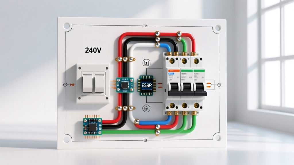
Before pulling any wire, you must understand the fundamental nodes on a standard 240V baseboard heater schematic. Unlike low-voltage HVAC systems that use a complex 8-wire thermostat harness, line-voltage baseboards rely on a much simpler, yet higher-risk, architecture.
- Line (L1, L2): The incoming power from the breaker panel. In a 240V setup, both wires are 'hot' (typically black and red in 12/2 or 12/3 NM-B cable).
- Load (T1, T2): The outgoing power from the thermostat to the heating element.
- Neutral (N): Required for 120V heaters and 2026-era smart thermostats. In a pure 240V mechanical setup, the neutral is often capped and unused at the thermostat box.
- Ground (G): The bare copper or green wire. Per NFPA NEC Article 250, the heater chassis and thermostat box must be bonded to ground.
The 125% Continuous Load Rule (NEC Article 424)
The most critical mistake DIYers make when reading an electric baseboard heater wiring schematic is sizing the breaker for the exact amperage of the unit. Under NEC Article 424.4(B), fixed electric space heating equipment is classified as a continuous load (operating for 3 hours or more). Therefore, the branch circuit conductors and overcurrent devices must be sized at 125% of the continuous load.
Code Calculation Example:
You are installing a Cadet F Series 1500W 240V baseboard heater.
1. Base Amperage: 1500W ÷ 240V = 6.25 Amps.
2. Continuous Load Multiplier: 6.25A × 1.25 = 7.81 Amps.
3. Breaker Sizing: A 15-Amp double-pole breaker is legally sufficient (15A > 7.81A).
4. Wire Sizing: While 14 AWG is rated for 15A, industry best practice in 2026 dictates using 12 AWG NM-B (rated for 20A) to mitigate voltage drop and accommodate future smart thermostat power draws.
Wire Gauge and Breaker Sizing Matrix
Use the following matrix to plan your rough-in. Pricing reflects average 2026 retail costs for copper NM-B (Romex) and standard QO/HOM breakers.
| Heater Wattage | Voltage | Base Amps | 125% NEC Amps | Min. Wire Gauge | Breaker Size | Est. Wire Cost (per ft) |
|---|---|---|---|---|---|---|
| 500W - 1000W | 240V | 2.1 - 4.1A | 2.6 - 5.2A | 14 AWG (12 AWG Rec.) | 15A (2-Pole) | $0.45 (14/2) |
| 1500W | 240V | 6.25A | 7.81A | 12 AWG | 15A or 20A (2-Pole) | $0.65 (12/2) |
| 2000W - 2500W | 240V | 8.3 - 10.4A | 10.4 - 13.0A | 12 AWG | 20A (2-Pole) | $0.65 (12/2) |
| 1500W | 120V | 12.5A | 15.6A | 12 AWG | 20A (1-Pole) | $0.60 (12/2) |
The 2026 Smart Thermostat Paradigm Shift
If your electric baseboard heater wiring schematic was drawn before 2015, it likely assumes a mechanical, line-voltage thermostat. Today, homeowners demand app-based control, geofencing, and energy reporting. This introduces a massive planning hurdle: The Neutral Wire Requirement.
Comparing 2026 Smart Thermostat Wiring Needs
- Mysa Smart Thermostat (V1-1): Requires Line, Load, and Neutral. If your existing schematic only has a 2-wire setup (no neutral at the switch box), you must either pull a new 12/3 NM-B cable from the panel or abandon this model.
- Sinopé TH1124WF: A brilliant workaround for older homes. It operates on a 2-wire system (Line and Load) by using a 'trickle current' through the heating element to power its Wi-Fi radio. Edge Case: This will not work with heaters that have built-in relays or certain low-mass mica heaters that block the trickle current.
Critical Edge Cases and Schematic Failure Modes
Even with a perfect schematic, real-world installation conditions can introduce dangerous failure modes. Watch out for these specific scenarios:
1. Multi-Wire Branch Circuits (MWBC) and Shared Neutrals
When wiring multiple 120V baseboard heaters in different rooms, electricians sometimes use a 12/3 cable to create an MWBC, sharing a single neutral wire between two hot legs. Crucial Code Requirement: The two breakers must be on opposite phases (240V across them) and must be tied together with a handle-tie or a 2-pole breaker. If they are accidentally placed on the same phase, the shared neutral will carry the sum of the currents rather than the difference, leading to melted insulation and a severe fire hazard.
2. Voltage Drop on Long Conduit Runs
If your breaker panel is on the opposite side of a large home, and the wire run to the baseboard heater exceeds 75 feet, a standard 12 AWG wire will experience noticeable voltage drop. A 240V heater receiving only 220V will produce roughly 16% less heat and draw higher amperage to compensate, stressing the circuit. For runs over 80 feet, upgrade your schematic to specify 10 AWG THHN pulled through 1/2-inch EMT conduit.
3. Solid-State 'Phantom Heating'
When using smart thermostats with TRIAC (solid-state) switching instead of mechanical relays, a tiny amount of current can 'leak' through the circuit even when the thermostat reads 'OFF'. With high-resistance baseboard elements, this is negligible. However, if you wire multiple low-wattage heaters in parallel on the same load line, this leakage can cause the heaters to remain lukewarm continuously. Always check the manufacturer's minimum wattage requirements for smart thermostats.
Step-by-Step Installation Planning Checklist
Before cutting into drywall or stripping wires, verify your plan against this checklist to ensure compliance with OSHA electrical safety standards and local building codes:
- Calculate Total Room Wattage: Use the rule of thumb: 10 Watts per square foot of floor space for standard 8-foot ceilings in a moderately insulated room.
- Verify Panel Capacity: Ensure your main service panel has at least two adjacent open slots for a 240V double-pole breaker, and that the main bus bar is not already maxed out (perform a NEC Article 220 load calculation).
- Determine Thermostat Type: Decide between mechanical, programmable, or Wi-Fi. If Wi-Fi, verify the presence of a neutral wire at the planned thermostat junction box.
- Map the Wire Route: Plan the NM-B cable route to avoid running directly above heating ducts or recessed lighting fixtures, which can degrade the wire insulation over time.
- Clearance Checks: Ensure the schematic places the heater at least 3/4 inch above the floor (for carpet clearance) and at least 12 inches away from any adjacent walls or furniture to prevent thermal cutoff switch tripping.
Final Thoughts on Schematic Execution
A properly executed electric baseboard heater wiring schematic is the backbone of a safe, efficient, and modern heating system. By respecting the 125% continuous load rule, anticipating the neutral wire requirements of 2026 smart home technology, and avoiding shared-neutral pitfalls, you ensure your installation will provide decades of reliable, silent heat. Always pull local permits and have your rough-in inspected by a licensed electrical inspector before energizing the circuit.