
The Hidden Danger in Dual Electric Fan Wiring Diagrams
Upgrading to a dual electric fan setup—whether for a high-horsepower V8 swap, a heavy-duty towing truck, or a custom radiator build—drastically improves cooling efficiency. However, the electrical demands of pushing two 16-inch or 14-inch fans simultaneously are massive. A poorly executed dual electric fan wiring diagram doesn't just result in blown fuses; it causes severe voltage drop, melted relay housings, and in extreme cases, engine bay fires.
Most generic wiring guides fail to address the critical nuances of wire gauge selection and automotive color coding. When you are pushing 40 to 60 amps of continuous current, standard household electrical rules do not apply. This guide provides a professional-grade reference for wire gauge sizing, SAE color codes, and the correct parallel relay topology to ensure your cooling system operates flawlessly.
Calculating Amperage: What Dual Fans Actually Draw
Before selecting your wire gauge, you must understand the true electrical load. Electric motors experience a massive inrush current (locked-rotor amperage) when they first start spinning. If you wire two fans to a single relay without accounting for this combined startup spike, the relay contacts will arc and weld shut.
| Fan Configuration (Dual) | Combined Running Amps | Combined Inrush (Startup) Amps | Recommended MAXI Fuse |
|---|---|---|---|
| Dual 12-Inch (Standard) | 18A - 22A | 45A - 55A | 40A MAXI |
| Dual 14-Inch (Standard) | 24A - 30A | 60A - 75A | 50A MAXI |
| Dual 16-Inch (High-CFM / Spal) | 36A - 44A | 90A - 110A | 60A or 70A MAXI |
Wire Gauge Selection: SAE J1128 vs. Standard AWG
Automotive wire is not the same as standard copper building wire. According to the SAE J1128 standard, automotive primary wire (like GXL or TXL) features cross-linked polyethylene insulation that withstands under-hood temperatures up to 125°C (257°F). Furthermore, automotive wire gauge sizing differs slightly from standard NEC AWG; an 8 AWG automotive wire may have a slightly different copper cross-section than 8 AWG THHN building wire.
The Voltage Drop Matrix for Dual Fan Circuits
Electric fans are highly sensitive to voltage drop. If your fan is rated to push 2,500 CFM at 13.8V, but your undersized wiring drops the voltage at the motor to 11.5V, the fan speed drops exponentially, and the amperage draw actually increases as the motor struggles, creating a thermal runaway scenario.
| Wire Gauge (SAE TXL/GXL) | Max Continuous Amps | Max Run Length (One Way) for <3% Drop @ 40A | Best Application in Dual Fan Setup |
|---|---|---|---|
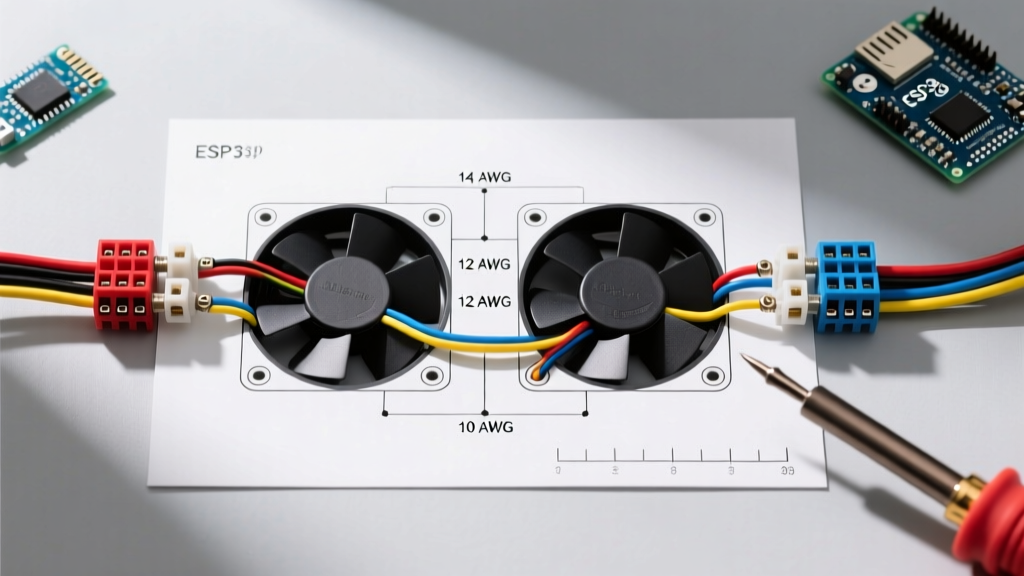
| 12 AWG | 20A | 4 feet | Thermostat trigger / Relay coil feed |
| 10 AWG | 30A | 6 feet | Single 14" fan power feed |
| 8 AWG | 50A | 10 feet | Main battery feed to dual relay bank |
| 6 AWG | 75A | 15 feet | High-CFM dual 16" fan main power trunk |
Pro-Tip: Always use a high-quality ratcheting crimping tool, such as the Titan 11477 or Knoweasy Wire Crimper, for 8 AWG and 6 AWG ring terminals. Soldering large-gauge automotive wire is discouraged by experts at MAD Electrical because solder wicks under the insulation, creating a stiff point that snaps under engine vibration. Always seal crimps with 3M FP-301 adhesive-lined heat shrink.
Automotive Color Code Standards for Cooling Circuits
While the NEC dictates color codes for residential AC wiring, 12V DC automotive circuits rely on established industry conventions. Adhering to these colors makes troubleshooting a melted harness significantly easier years down the road.
- Red (Main Power): Unswitched 12V+ directly from the battery or main distribution block. Used from the battery to the MAXI fuse, and from the fuse to Relay Terminal 30.
- Black (Main Ground): High-amperage ground paths. Used from the fan motor negative terminal to the chassis ground stud, and from Relay Terminal 85 to ground.
- Yellow or Blue (Switched Trigger): Low-amperage 12V+ trigger signals. Used from the thermostat probe switch or ECU fan-control pin to Relay Terminal 86.
- White or Light Blue (Fan Load): The switched high-amperage output. Used from Relay Terminal 87 to the positive brush terminal on the electric fan motors.
Step-by-Step: The Dual-Relay Parallel Wiring Flow
The most common mistake in a dual electric fan wiring diagram is wiring both fans to a single 40A relay. The combined inrush current will destroy the relay contacts. The professional method is a Parallel Dual-Relay Setup, utilizing two independent 40A or 50A Bosch-style relays (e.g., Hella 4RA 003 510-081) triggered by a single thermostat switch.
- Main Power Feed: Run 8 AWG Red wire from the battery positive terminal to a 60A MAXI fuse holder mounted within 18 inches of the battery.
- Power Distribution: From the fuse, run 8 AWG Red wire to a heavy-duty distribution block, then split to both Relay 1 (Terminal 30) and Relay 2 (Terminal 30).
- Fan Load Wiring: Run 10 AWG White wire from Relay 1 (Terminal 87) to Fan 1 Positive. Run 10 AWG White wire from Relay 2 (Terminal 87) to Fan 2 Positive.
- Grounding the Motors: Run 10 AWG Black wire from both fan negative terminals to a dedicated, bare-metal chassis ground stud. Never ground high-draw fans to the radiator support or aluminum core support.
- Relay Coil Ground: Wire both Relay 1 and Relay 2 (Terminal 85) to a clean chassis ground using 12 AWG Black wire.
- Thermostat Trigger: Run 12 AWG Yellow wire from your coolant temperature switch (e.g., Derale 16749 or factory ECU pin) to both Relay 1 and Relay 2 (Terminal 86). When the temp switch closes, it provides the low-amp ground/trigger to fire both relays simultaneously.
Expert Insight: If your vehicle uses a modern ECU to control the fans via a low-side driver (switched ground), you must reverse the coil wiring. Connect Terminal 86 to a switched 12V+ ignition source, and route Terminal 85 to the ECU's fan control pin. Always check the ECU's maximum current sink rating; if it's under 1.5A, use an intermediate isolation relay to protect the ECU.
Real-World Failure Modes and Edge Cases
Even with a perfect diagram, physical installation errors cause system failures. Watch out for these specific edge cases:
1. Relay Coil Chatter and Voltage Starvation
If your alternator is undersized (e.g., a stock 65A alternator on a truck with dual 16" fans, a fuel pump, and an MSD ignition), the system voltage at idle may drop below 12.5V when the fans kick on. This causes the relay electromagnetic coil to weaken, resulting in "chatter" (rapidly opening and closing). This arcing will melt the relay socket. Solution: Upgrade to a 130A+ high-output alternator (like a Powermaster 47294) and ensure the alternator-to-battery positive cable is upgraded to 4 AWG.
2. The "Daisy Chain" Ground Failure
Daisy-chaining the ground wire from Fan 1 to Fan 2 is a critical error. If the crimp at Fan 1 fails, Fan 2 will attempt to ground through Fan 1's internal circuitry, potentially back-feeding voltage and frying the motor windings. Always run independent, parallel ground wires from each motor back to a central ground busbar or chassis stud.
3. Thermal Overload of Cheap Relays
Many auto parts store relays are labeled "40A" but use inferior internal copper alloys that overheat at 25A continuous. For dual fan setups that run for hours in stop-and-go traffic, invest in heavy-duty relays with integrated thermal protection or use solid-state automotive contactors (like the Painless Performance solid-state fan controllers) which eliminate mechanical arcing entirely. For comprehensive harness and relay tech specs, consult the engineering resources at Painless Performance.
Final Verification Checklist
Before applying power, verify your dual electric fan wiring diagram execution:
- Main fuse is rated 125% of the combined continuous running amps.
- All high-amp crimps are sealed with adhesive-lined heat shrink.
- Ground terminals are bolted to bare metal, treated with anti-oxidant paste (like NOALOX) to prevent corrosion.
- Wires are routed away from exhaust headers and moving belt assemblies, secured with split-loom and Tesa tape.