
The Hidden Fire Hazards of High-Amperage Cooling Fans
Integrating an aftermarket electric radiator fan into a vehicle or industrial cooling system is one of the most common electrical modifications performed today. However, a poorly executed electric radiator fan wiring diagram is a leading cause of engine bay fires. High-performance 16-inch dual fans, such as the Spal 30102804 or Flex-a-lite 216 Black Magic, can draw between 25 and 35 amps continuously, with inrush currents spiking past 50 amps upon startup. If your wiring topology relies on undersized PVC wire or cheap 30A micro-relays, you are actively creating a thermal runaway hazard.
From a safety and code compliance perspective, automotive and stationary cooling circuits must adhere to strict guidelines regarding wire insulation temperature ratings, circuit protection coordination, and voltage drop limits. This guide provides a fail-safe, SAE-compliant wiring methodology to ensure your cooling system operates reliably without risking catastrophic electrical failure.
Core SAE Standards for Cooling Circuit Compliance
Unlike residential wiring governed by the NEC (NFPA 70), mobile and automotive electrical systems are regulated by the Society of Automotive Engineers (SAE). When designing your electric radiator fan wiring diagram, two specific standards dictate your component selection:
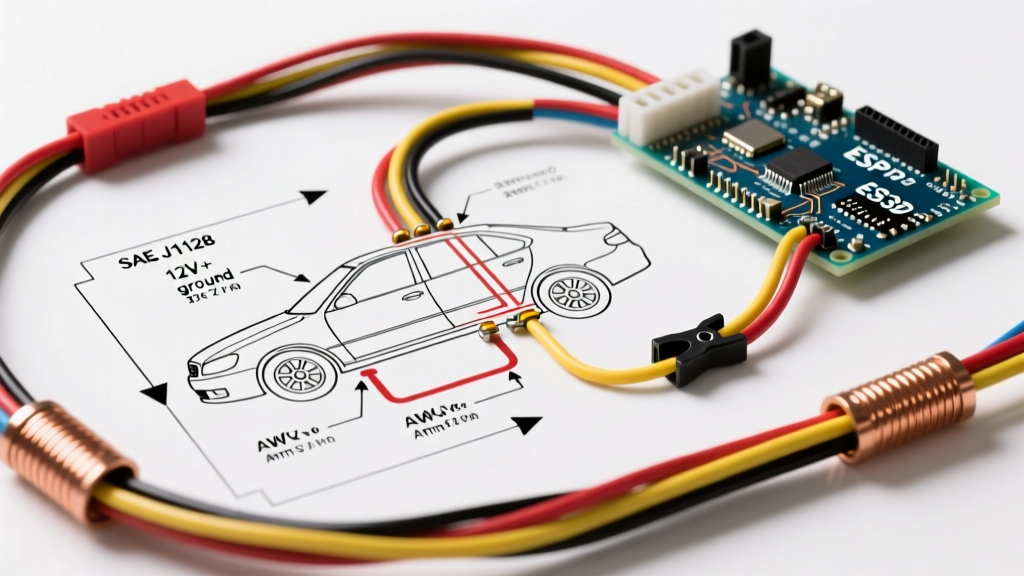
- SAE J1128 (Low Tension Primary Cable): Dictates the requirements for wire insulation. Standard PVC primary wire (GPT) is rated for 90°C. In a modern engine bay where ambient temperatures routinely exceed 110°C, GPT wire insulation will soften, melt, and short against the chassis. You must use Cross-Linked Polyethylene (TXL, GXL, or SXL) wire, which is rated for 125°C to 150°C. Learn more about primary cable specifications at the SAE J1128 standard page.
- SAE J553 (Circuit Protectors): Governs the selection of fuses and circuit breakers. A common and dangerous mistake is using a standard ATO/ATC blade fuse for a 30A fan circuit. Blade fuses are not designed to handle the high inrush currents of electric motors without premature fatigue. You must utilize MAXI, MIDI, or AMEGA style fuses for high-amperage motor circuits. Refer to the SAE J553 circuit protector guidelines for exact trip-curve matching.
Wire Gauge Selection: The Math Behind the Diagram
Wire gauge selection is not just about preventing the wire from melting; it is about minimizing voltage drop to ensure the fan motor receives adequate voltage. A voltage drop greater than 3% (0.36V on a 12V system) causes the motor to draw excess amperage to compensate for the lack of power, leading to premature motor burnout.
| Wire Gauge (AWG) | Max Continuous Amps (SAE) | Resistance (Ohms/1000ft) | Voltage Drop (20ft round trip @ 30A) | Compliance Verdict |
|---|---|---|---|---|
| 12 AWG TXL | 25A | 1.588 | 0.95V (7.9%) | FAIL - Fire/Motor Risk |
| 10 AWG TXL | 35A | 0.998 | 0.60V (5.0%) | MARGINAL - Short runs only |
| 8 AWG TXL | 50A | 0.628 | 0.37V (3.1%) | PASS - Recommended Standard |
| 6 AWG TXL | 70A | 0.395 | 0.23V (1.9%) | OPTIMAL - Dual fan setups |
Note: The 20ft round trip assumes a 10-foot run from the battery to the relay, and a 10-foot ground return path to the chassis. Always measure your actual wire run length.
The Fail-Safe Electric Radiator Fan Wiring Diagram (Step-by-Step)
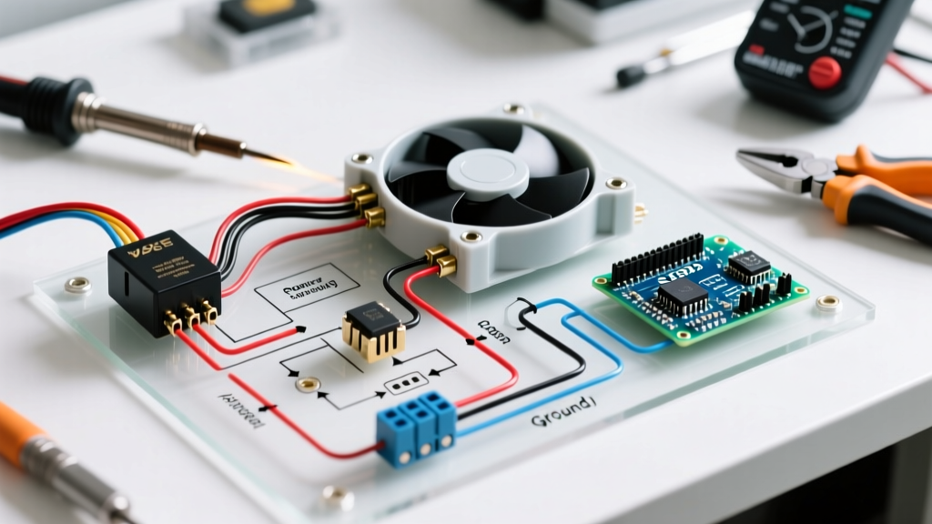
Below is the exact circuit topology required for a safe, high-amperage single or dual electric fan setup. This diagram isolates the high-current motor circuit from the low-current switching circuit, protecting your vehicle's ECU and interior switches.
1. The High-Current Power Circuit (Pins 30 & 87)
- Battery to Fuse: Run 8 AWG TXL wire directly from the positive battery terminal to a 50A MIDI fuse holder mounted within 6 inches of the battery. This protects the entire downstream run in the event of a dead short.
- Fuse to Relay (Pin 30): Continue the 8 AWG wire from the fuse to Pin 30 (Power In) of a heavy-duty 50A ISO mini relay.
- Relay to Fan (Pin 87): Run 8 AWG wire from Pin 87 (Power Out) to the positive terminal of the electric radiator fan motor.
- Fan Ground: Run 8 AWG wire from the fan's negative terminal directly to a clean, bare-metal grounding point on the chassis or engine block. Use a star washer and apply dielectric grease to prevent corrosion.
2. The Low-Current Control Circuit (Pins 85 & 86)
- Ignition Power to Pin 86: Run 16 AWG GXL wire from a switched 12V ignition source (fused at 5A) to Pin 86 on the relay. This ensures the fan cannot run if the key is off, preventing battery drain.
- Thermal Switch to Pin 85: Run 16 AWG wire from Pin 85 to your thermal switch or ECU fan control output. The thermal switch completes the circuit to ground when the coolant reaches the preset temperature (e.g., 195°F).
CRITICAL SAFETY WARNING: Never wire the thermal switch on the high-amperage side of the circuit. Passing 30A through a standard brass thermal switch (like the Hayden 3647) will cause the internal bi-metallic strip to arc, weld shut, and fail in the 'ON' position, resulting in a continuously running fan and eventual alternator failure.
Component Deep Dive: Relays and Fuses
The reliability of your electric radiator fan wiring diagram hinges entirely on the quality of the switching and protection components. The market is currently flooded with counterfeit and under-specced relays. Below is a comparison matrix to guide your 2026 purchasing decisions.
| Component Type | Example Model / Spec | Estimated Cost (2026) | Safety & Performance Profile |
|---|---|---|---|
| Standard 30A Bosch-Style Relay | Generic Import (No Brand) | $3.00 - $5.00 | High failure rate. Contacts weld under 25A+ inrush. Avoid completely. |
| Heavy Duty 50A ISO Relay | TE Connectivity V23134 | $14.00 - $18.00 | Excellent. Designed for high inrush motor loads. Silver alloy contacts prevent welding. |
| Solid State Relay (SSR) | Crydom D1240 | $45.00 - $60.00 | Superior lifespan (no moving parts), but requires a dedicated heatsink due to thermal dissipation. |
| Standard ATO Blade Fuse (30A) | Littelfuse ATOF030 | $0.50 | Poor for motors. Fatigue from inrush current causes nuisance blowing. See Littelfuse automotive fuse data. |
| MIDI / AMEGA Fuse (50A) | Littelfuse 0298050 | $3.50 - $5.00 | Optimal. Slow-blow characteristics handle motor startup spikes without thermal fatigue. |
Common Failure Modes & Edge Cases
Even with a perfect schematic, physical installation errors can compromise the system. Be vigilant against these specific failure modes:
- Ground Loop Interference: If you ground the high-amperage fan motor to the same chassis stud as your ECU or sensitive sensor grounds, the massive current return path will induce voltage fluctuations (ground loops). This can cause erratic idle, sensor faults, and ECU resets. Always use a dedicated, isolated ground stud for high-amperage cooling fans.
- Thermal Switch Hysteresis: Cheap probe-style thermal switches that strap to the outside of the radiator hose suffer from severe hysteresis and delayed reaction times. By the time the switch reads 210°F on the outside of a silicone hose, the internal coolant may already be boiling at 235°F. Always use threaded brass switches installed directly into the radiator neck, engine block, or a dedicated welded bung on the upper radiator hose.
- Voltage Drop Induced Thermal Runaway: As mentioned in the gauge table, undersized wires drop voltage. Electric motors are constant-power devices; if voltage drops, amperage increases to maintain wattage (Watts = Volts x Amps). This increased amperage generates exponential heat in the wire (Heat = I²R), melting the insulation and causing a dead short.
Code Compliance & Inspection Checklist
Before energizing your electric radiator fan circuit, run through this mandatory safety checklist to ensure compliance with automotive electrical best practices:
- [ ] Wire insulation is rated for at least 125°C (TXL/GXL/SXL).
- [ ] Main power fuse is located within 6 inches of the battery positive terminal.
- [ ] Fuse rating is 125% to 150% of the fan's continuous amperage draw (e.g., 40A-50A fuse for a 25A fan).
- [ ] Relay is rated for a minimum of 50A (or matches the exact continuous draw + 20% margin if using a premium SSR).
- [ ] All high-current connections are crimped using a closed-barrel, ratcheting crimper and sealed with adhesive-lined heat shrink.
- [ ] The control circuit (Pins 85/86) is fused independently at 5A to protect the thermal switch and wiring.
- [ ] Fan motor ground is isolated from ECU and sensor grounds.
Conclusion
Designing a safe and reliable electric radiator fan wiring diagram requires moving beyond generic internet schematics and applying rigorous electrical engineering principles. By adhering to SAE J1128 for wire selection, utilizing SAE J553 compliant circuit protectors, and isolating your high-amperage motor loads from sensitive control circuits, you eliminate the risk of engine bay fires and ensure your cooling system performs flawlessly under the most demanding thermal loads. Never compromise on wire gauge or relay quality; the cost of an 8 AWG TXL wire harness and a genuine TE Connectivity relay is a fraction of the cost of replacing a melted wiring harness or a destroyed engine.