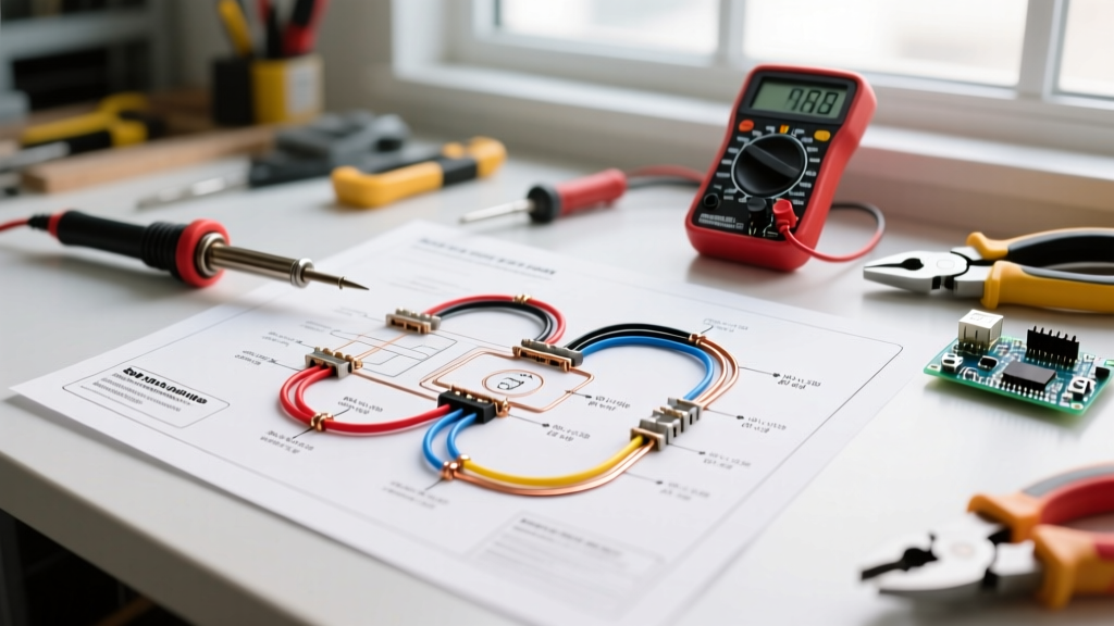

The Regulatory Baseline: DOT, FMCSA, and SAE Standards
When dealing with trailer electric brake wiring schematics, treating the process as a simple DIY afterthought is a critical safety hazard. Improperly wired electric brakes lead to voltage drops, delayed braking response, and in worst-case scenarios, electrical fires in the trailer tongue or tow vehicle chassis. From a compliance perspective, your wiring must adhere to strict federal and industry guidelines.
The Federal Motor Carrier Safety Administration (FMCSA) under 49 CFR § 393.42 mandates that any trailer with a Gross Vehicle Weight Rating (GVWR) exceeding 3,000 lbs must have brakes acting on all wheels. While the DOT regulates the mechanical presence of the brakes, the electrical actuation falls under the purview of SAE International standards (specifically SAE J286 for light-duty 7-way connectors) and the National Electrical Code (NEC) Article 551/552 for recreational vehicles. Ignoring these schematic standards doesn't just risk a failed DOT inspection; it compromises the pulse-width modulation (PWM) signals required by modern brake controllers.
Decoding the 7-Way RV Blade: Pinout and Schematic Logic
The industry standard for electric trailer brakes is the 7-way RV blade connector. Understanding the exact pinout is the foundation of any compliant schematic. Misrouting the 12V auxiliary power into the brake circuit will instantly fry the brake controller's internal MOSFETs.
| Pin Position | Function | Standard Wire Color | Wire Gauge (Min) | Circuit Protection |
|---|---|---|---|---|
| Pin 1 (Top) | Ground Return | White | 10 AWG | N/A (Main Ground) |
| Pin 2 (Top Right) | Electric Brakes | Blue | 12 AWG - 8 AWG | 30A - 50A Auto-Reset Breaker |
| Pin 3 (Bottom Right) | Tail/Running Lights | Brown | 16 AWG | 15A Fuse |
| Pin 4 (Center) | 12V Auxiliary Power | Black | 10 AWG | 40A Auto-Reset Breaker |
| Pin 5 (Bottom Left) | Right Turn/Brake | Green | 16 AWG | 15A Fuse |
| Pin 6 (Top Left) | Left Turn/Brake | Yellow | 16 AWG | 15A Fuse |
| Pin 7 (Bottom Center) | Reverse Lights / Aux | Purple | 16 AWG | 15A Fuse |
Wire Gauge, Breaker Sizing, and Voltage Drop Matrix
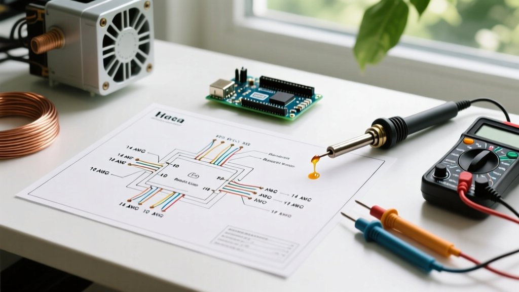
The most common code violation in trailer brake schematics is undersizing the blue brake wire. Electric brake magnets typically draw 3.0 to 3.5 amps each at 12V DC. A tandem-axle trailer (4 brakes) will pull up to 14 amps under full lock. However, wire gauge selection must account for the total round-trip distance from the tow vehicle battery, through the controller, to the trailer axles, and back to the ground.
Sizing Matrix by Trailer Configuration
- Single Axle (Up to 15 ft total run): 12 AWG Blue Wire | 30A Circuit Breaker | Max Voltage Drop: 0.6V
- Tandem Axle (15 ft to 25 ft total run): 10 AWG Blue Wire | 40A Circuit Breaker | Max Voltage Drop: 0.5V
- Triple Axle (25 ft+ total run): 8 AWG Blue Wire | 50A Circuit Breaker | Max Voltage Drop: 0.4V
Expert Insight: Never use standard automotive blade fuses for the main electric brake circuit. You must use a slow-blow, auto-resetting thermal circuit breaker (like the Bussmann CB184 series). Brake magnets create a massive inductive inrush current when first energized; a standard glass or blade fuse will nuisance-blow under heavy braking, leaving you with zero trailer brakes on the highway.
Step-by-Step Fail-Safe Routing & Grounding Protocols
According to data compiled by etrailer's wiring diagnostics team, over 70% of 'failed brake controller' returns are actually caused by poor ground returns, not faulty controllers. Your schematic must prioritize the ground path as much as the 12V supply.
- Establish a Dedicated Star Ground: Do not daisy-chain the ground wire from the left brake to the right brake. Run a dedicated 10 AWG white ground wire from the 7-way plug directly to a central, bare-metal grounding block on the trailer frame.
- Frame Preparation: Use a wire wheel to strip away paint, powder coating, and rust down to bare steel at the grounding point. Apply a coating of dielectric grease (e.g., Permatex 22058) after torquing the ring terminal to prevent oxidation without impeding conductivity.
- Individual Magnet Grounding: Run 12 AWG white wires from each individual brake magnet back to the central grounding block. This ensures that if one magnet's ground wire chafes and breaks, the remaining brakes maintain a solid return path.
- Breakaway Switch Integration: The breakaway switch must be wired in parallel with the brake controller output. Wire one side of the breakaway switch to the 12V auxiliary battery (via a 20A breaker) and the other side directly to the blue brake wire after the 7-way plug. Never wire the breakaway switch through the tow vehicle's wiring harness.
Edge Cases: Troubleshooting Backfeed and Ground Loops
When executing complex trailer electric brake wiring schematics, especially on aluminum-frame trailers or those with surge-brake lockout solenoids, edge cases emerge that standard diagrams ignore.
The Aluminum Frame Ground Loop
Aluminum oxidizes rapidly, creating a high-resistance dielectric layer. If you are wiring an aluminum boat trailer or utility trailer, the frame cannot be used as a ground return path. You must run a dedicated 10 AWG white copper wire the entire length of the trailer, physically bonding it to each axle hub using stainless steel star washers to bite through the aluminum oxide layer.
Backfeed Through the Breakaway Switch
If your brake controller display shows power output when the trailer is disconnected and the breakaway pin is pulled, you have a backfeed issue. This occurs when the breakaway battery is wired to the same terminal as the 7-way blue wire without a blocking diode. While rare in modern controllers like the Tekonsha Prodigy P3 (Part #90195, ~$145) due to internal isolation, older time-delayed controllers can suffer MOSFET burnout from reverse voltage spikes when the breakaway switch is disengaged.
2026 Component Selection and Controller Compatibility
Modern proportional brake controllers utilize high-frequency Pulse Width Modulation (PWM) to simulate smooth hydraulic braking. Your wiring schematic must support clean signal transmission without electromagnetic interference (EMI).
- Tekonsha Prodigy P3 (90195): The industry benchmark. Requires strict adherence to 10 AWG power and ground wires at the controller pigtail to handle its rapid PWM switching without voltage sag. Retail: ~$145.
- Curt Spectrum (51156): Features a unique rotary dial and internal inertia sensor. Highly sensitive to ground loop noise; requires a dedicated star ground on the tow vehicle chassis, not just a battery negative terminal. Retail: ~$115.
- Redarc Tow-Pro Elite: Popular in overland and off-road builds. Requires a 30A auto-reset breaker and heavily shielded wiring if routed near aftermarket winch solenoids or high-amperage DC-DC chargers. Retail: ~$220.
For authoritative safety guidelines regarding towing dynamics and brake requirements, always consult the NHTSA Trailer Towing Safety portal before finalizing your schematic for heavy-duty applications.
Final Inspection Checklist
Before taking the rig on the road, perform this DOT-aligned compliance check:
- Verify all wire connections use adhesive-lined heat shrink (minimum 3:1 shrink ratio), never electrical tape.
- Confirm the blue brake wire is routed at least 6 inches away from high-current DC-DC charger lines to prevent inductive cross-talk.
- Test the voltage at the furthest brake magnet with the controller manually set to 100% output. You should read no less than 11.2V DC. Anything lower indicates an undersized wire or a high-resistance ground.