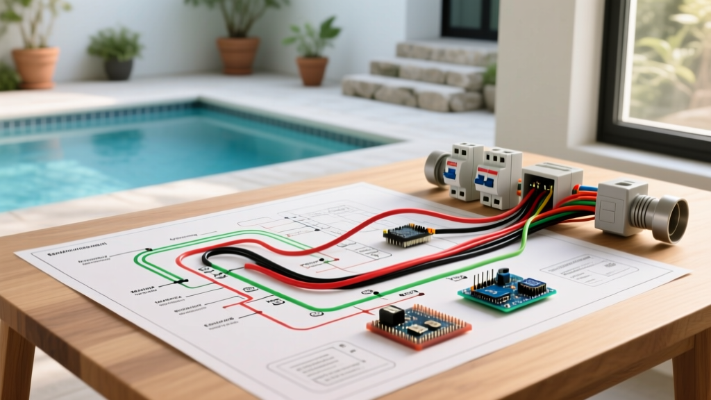

Decoding the Swimming Pool Electrical Wiring Diagram
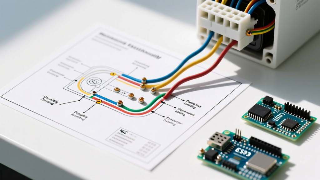
Planning the electrical infrastructure for a residential or commercial pool requires more than just connecting a pump to a breaker. A comprehensive swimming pool electrical wiring diagram serves as the blueprint for safety, code compliance, and long-term equipment reliability. In 2026, with the widespread adoption of advanced variable speed pumps (VSPs) and automated saltwater chlorine generators (SWGs), the complexity of these diagrams has increased significantly. This installation planning guide breaks down the critical components, wire sizing, and National Electrical Code (NEC) Article 680 requirements necessary to execute a flawless, inspection-ready pool electrical build.
The Anatomy of a Compliant Pool Electrical System
Before pulling any wire through conduit, your swimming pool electrical wiring diagram must account for three distinct systems: the power delivery circuit, the equipment grounding conductor (EGC), and the equipotential bonding grid. Confusing the EGC with the bonding grid is the most common failure mode among novice installers. While the EGC provides a low-impedance path back to the panel to trip the breaker during a fault, the bonding grid equalizes electrical potential across all metal components so that a person never becomes the path of least resistance.
Subpanel and GFCI Protection Requirements
Modern pool installations almost universally require a dedicated outdoor subpanel. According to the NFPA 70 National Electrical Code, all pool pump motors, regardless of voltage (120V or 240V), must be protected by a Ground Fault Circuit Interrupter (GFCI). For a standard 240V VSP like the Pentair IntelliFlo VSF, your diagram must specify a 2-pole, 240V GFCI breaker (such as the Square D QO220GFIC or Eaton BR220GF), typically rated at 20A or 30A depending on the motor's full load amps (FLA).
Material & Wire Sizing Planning Matrix
Accurate material estimation prevents costly mid-project delays. The table below outlines the standard specifications for a typical residential pool setup featuring a 3 HP variable speed pump, a 400,000 BTU gas heater, and underwater LED lighting.
| System Component | Wire Gauge (THWN-2) | Breaker Type & Size | Est. Material Cost (2026) |
|---|---|---|---|
| 3 HP VSP (240V) | #10 AWG (3 conductors + EGC) | 2-Pole 20A GFCI | $140 - $180 |
| Gas Heater (240V) | #12 AWG (2 conductors + EGC) | 2-Pole 20A Standard | $45 - $60 |
| LED Pool Light (120V) | #12 AWG (1 conductor + EGC) | 1-Pole 15A GFCI | $35 - $50 |
| Saltwater Generator | #12 AWG (2 conductors + EGC) | 2-Pole 15A Standard | $40 - $55 |
| Equipotential Bonding | #8 AWG Solid Bare Copper | N/A (Not a current-carrying circuit) | $90 - $120 |
Note: All conductors inside outdoor wet-location conduits must be rated THWN or THWN-2. Never use standard THHN indoors-only wire for underground pool runs, as moisture ingress will degrade the insulation over time.
Equipotential Bonding: The Critical Safety Grid
The equipotential bonding grid is the most heavily scrutinized element during an electrical inspection. Your swimming pool electrical wiring diagram must detail a continuous #8 AWG solid bare copper wire connecting all metallic parts within 5 feet of the pool's inside wall. This includes:
- The pool pump motor housing and metal base.
- Metal ladders, diving stands, and handrails.
- The pool shell reinforcing steel (rebar), tied together at multiple points with steel tie-wire or copper clamps.
- Metal parts of the pool water circulating system (filter tanks, metal valves, heater manifolds).
- Any metal piping or conduit within the 5-foot perimeter.
The Water Bonding Edge Case
A frequently overlooked NEC 680.26(C) requirement is the bonding of the pool water itself. If your pool construction utilizes PVC plumbing and a fiberglass or vinyl shell with no metal components in direct contact with the water, the water remains unbonded. In this scenario, your diagram must include a specialized water bonding device, such as the Polar Water Bond or a similar inline fitting with a copper insert, connected directly to the #8 AWG bonding grid. Failing to bond the water can result in a dangerous voltage gradient between the water and the surrounding deck.
Variable Speed Pump (VSP) & Automation Integration
When wiring modern automation systems like the Hayward OmniLogic or Pentair IntelliCenter, the wiring diagram expands to include low-voltage communication cables. These RS-485 communication cables must be routed in a separate conduit from the high-voltage 120V/240V power lines to prevent electromagnetic interference (EMI), which can cause erratic pump behavior or SWG communication dropouts. Maintain a minimum separation of 6 inches between high-voltage and low-voltage conduits, or use grounded metal barriers if they must cross paths.
Common Inspection Failures & Troubleshooting
Even experienced electricians can stumble on pool-specific codes. The International Association of Electrical Inspectors (IAEI) frequently highlights the following edge cases that lead to failed inspections:
- Using Stranded Wire for Bonding: NEC explicitly requires solid copper wire for the equipotential bonding grid. Stranded #8 AWG is a violation and will fail inspection.
- Missing the Equipment Grounding Conductor in PVC: When using non-metallic PVC conduit for underground runs, you cannot rely on the earth or the water pipe for grounding. You must pull a dedicated, insulated green Equipment Grounding Conductor (EGC) sized according to NEC Table 250.122 (minimum #12 AWG for 20A circuits, #10 AWG for 30A circuits).
- Improper Burial Depth: Rigid metal conduit (RMC) requires 6 inches of cover, while PVC conduit requires 18 inches of cover. Failing to account for the final grade level when trenching is a frequent cause of re-work.
- GFCI Nuisance Tripping on Older Heaters: While pool pumps require GFCI protection, some older gas heaters with standing pilot lights or specific ignition transformers may experience nuisance tripping on GFCI breakers. Always verify the heater manufacturer's specific GFCI compatibility guidelines before finalizing the diagram.
Expert Planning Tip: Always coordinate with the pool builder and the Association of Pool & Spa Professionals (APSP) certified technician before finalizing your conduit stub-outs. The placement of the automation control panel, the pump pad, and the heater must align perfectly with your underground trenching plan to avoid awkward above-ground conduit bends that violate the 5-foot bonding perimeter rules.
Finalizing Your Installation Blueprint
A meticulously planned swimming pool electrical wiring diagram is your best defense against costly rework and, more importantly, electrical hazards. By strictly adhering to NEC Article 680, specifying THWN-2 conductors, utilizing solid #8 AWG copper for bonding, and integrating GFCI protection at the breaker level, you ensure a system that is both highly efficient and inherently safe. Always submit your finalized diagram to your local Authority Having Jurisdiction (AHJ) for pre-approval before breaking ground, ensuring your specific regional amendments are fully addressed.