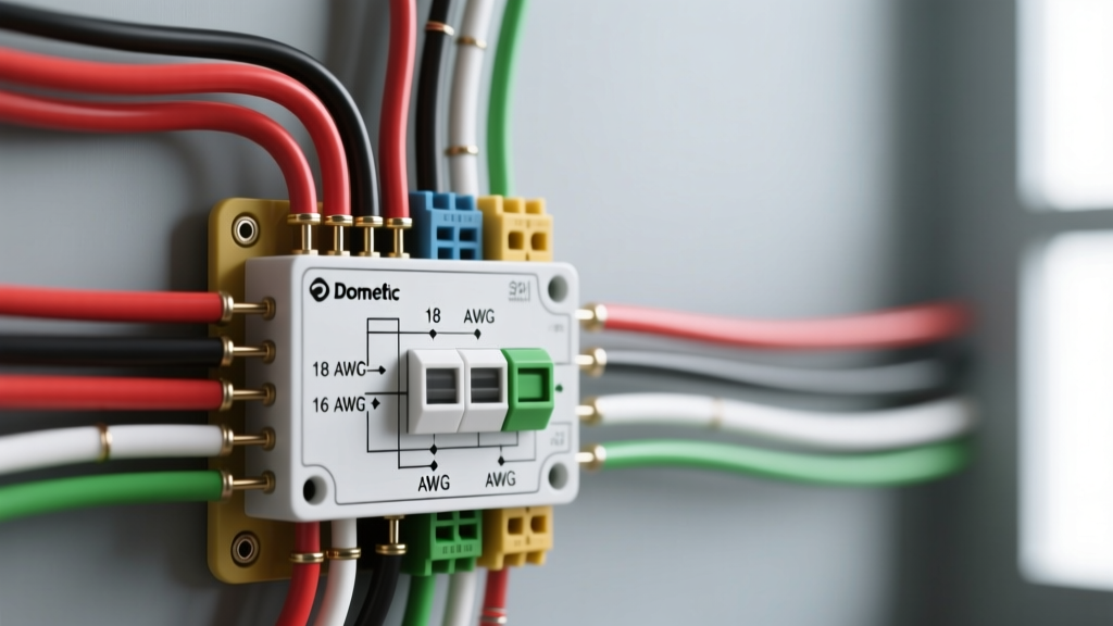

Understanding Dometic HVAC Architecture in Modern RVs
When upgrading or repairing recreational vehicle climate control systems, interpreting the correct wiring diagram for Dometic thermostat configurations is critical. Unlike residential HVAC systems that rely on 24V AC control circuits, Dometic RV systems utilize a 12V DC low-voltage communication bus between the wall-mounted thermostat and the roof-mounted air conditioning unit. As of 2026, with the widespread adoption of high-efficiency inverter compressors and digital communication protocols in models like the Dometic CT (Comfort Control) and CCC2 (Comfort Control Center 2), precise wire gauge selection and strict adherence to color codes are mandatory to prevent electromagnetic interference (EMI) and voltage drop.
Expert Insight: The most common cause of 'E-01' or 'E-04' communication errors in Dometic systems is not a failed control board, but rather excessive voltage drop on the 12V DC power feed due to undersized wiring over long RV cable runs. Always verify wire gauge before replacing expensive components.Wire Gauge Selection: Mitigating 12V Voltage Drop
The physical distance between the RV's main 12V DC distribution panel, the wall thermostat, and the roof unit dictates your wire gauge. The Recreational Vehicle Industry Association (RVIA) and NFPA 1192 standards mandate strict voltage drop limits for low-voltage control circuits. A standard Dometic CT thermostat draws approximately 150mA to 300mA, but the roof unit control board requires a minimum of 10.5V DC to reliably close the compressor contactor and initialize the communication handshake.
RV Wire Gauge Reference Matrix for Dometic Systems
| Application | Recommended AWG | Max Run Length (One Way) | Voltage Drop at Max Length |
|---|---|---|---|
| Thermostat 12V DC Power (Red/Black) | 18 AWG Stranded | 20 feet | < 3% (0.36V) |
| Thermostat 12V DC Power (Long Runs) | 16 AWG Stranded | 35 feet | < 3% (0.36V) |
| Communication / Data Bus (Yellow) | 18 AWG Shielded | 40 feet | N/A (Signal Integrity) |
| Roof Unit 120V AC Main Feed | 12 AWG Solid/Stranded | 50 feet | < 3% (3.6V) |
| High-Capacity Heat Strip (120V AC) | 10 AWG Solid/Stranded | 40 feet | < 3% (3.6V) |
Note: Always use copper stranded wire for 12V DC RV applications. Solid core wire is prone to metal fatigue and fracturing due to the constant vibration and torsional flexing of a moving vehicle.
Decoding the Wiring Diagram for Dometic Thermostat Systems
Dometic utilizes several thermostat platforms. The two most prevalent in the field are the analog/digital single-zone CT thermostat and the digital multi-zone CCC2 system. Understanding the specific pinout and color code for your model is essential for accurate termination.
Dometic CT Single-Zone (4-Pin) Color Codes
The standard Dometic CT thermostat (often part number 3106463.007) uses a simple 4-pin Molex-style connector. The wiring harness routes directly from the thermostat to the roof unit's main control board.
- Red Wire (+12V DC): Provides constant 12V power to the thermostat display and logic board. Must be connected to a fused 12V source (typically a 5A or 10A fuse at the distribution panel).
- Black Wire (Ground): 12V DC chassis ground. Must terminate at a clean, bare-metal grounding bus bar. Do not daisy-chain this ground with high-draw appliances like water pumps.
- Yellow Wire (Communication/Data): Carries the digital pulse-width modulation (PWM) signal to the roof unit. This wire dictates fan speed, compressor staging, and mode selection.
- Green Wire (Furnace/Accessory): Used exclusively if the RV integrates a Dometic or compatible 12V DC propane furnace. It sends a 12V trigger signal to close the furnace relay.
Dometic CCC2 Multi-Zone Pinouts
The CCC2 system (e.g., model 3314082.000) uses a more complex 6-pin or RJ-style modular connector to support multiple roof units and heat pumps. The color coding shifts slightly to accommodate the expanded data bus:
- Red: +12V DC Power
- Black: 12V DC Ground
- Yellow: Data Bus (+) / Communication High
- Green: Data Bus (-) / Communication Low
- Blue: Zone 2 / Second Stage Heat Pump Control
- White: Shield / Drain Wire (Must be grounded at the roof unit only to prevent ground loops)
Step-by-Step Routing and Termination Best Practices
Proper execution of the wiring diagram ensures long-term reliability. Follow these field-tested steps for termination:
- Disconnect All Power: Shut off the 120V AC main breaker and pull the 12V DC fuses for the HVAC system. Verify zero voltage with a multimeter.
- Route Away from EMI Sources: Keep the Yellow/Green communication wires at least 4 inches away from 120V AC inverter cables and fluorescent light ballasts to prevent signal degradation.
- Use Ferrule Crimps: Do not simply twist stranded wire and shove it into screw terminals. Use 18 AWG bootlace ferrules crimped with a ratcheting crimper to prevent stray strands from causing short circuits on the PCB.
- Apply Dielectric Grease: Coat the 4-pin or 6-pin Molex connectors with marine-grade dielectric grease before mating them to the roof unit to prevent oxidation in high-humidity environments.
Advanced Troubleshooting and Edge Cases
When the physical wiring matches the diagram but the system fails, use these diagnostic parameters to isolate the fault:
Diagnosing 'E-01' and 'E-04' Communication Errors
An 'E-01' code indicates the thermostat cannot detect the roof unit, while 'E-04' indicates a loss of communication mid-cycle.
The Fix: Measure the DC voltage at the roof unit's terminal block while the thermostat is calling for cooling. If the Red wire reads below 10.8V under load, you have excessive voltage drop. Upgrading the Red and Black wires from 18 AWG to 14 AWG for the main trunk run usually resolves this immediately.
Parasitic Draw and the 'Blank Screen' Issue
If the Dometic CT thermostat screen goes blank after the RV sits in storage for a week, the internal logic board may be failing to enter sleep mode, drawing up to 150mA continuously. While replacing the thermostat is the standard fix, verifying that the Black ground wire has less than 0.1 ohms of resistance to the battery negative terminal is a prerequisite, as a floating ground can corrupt the thermostat's internal EEPROM, causing erratic power states.
Industry Standards and Authoritative References
All wiring practices, gauge selections, and safety protocols outlined in this guide comply with current electrical and RV manufacturing standards. For further technical validation, consult the following resources:
- NFPA 1192 Standard on Recreational Vehicles: Governs low-voltage wiring methods, overcurrent protection, and voltage drop limits in RVs. Read the standard details at the National Fire Protection Association.
- Dometic Technical Support & Manuals: Access official wiring schematics, dip-switch configurations, and error code matrices for CT and CCC2 systems via the Dometic Official Support Portal.
- NFPA 70 (National Electrical Code): Article 551 covers specific electrical requirements for recreational vehicles and parks, including 120V AC feed sizing for roof-mounted HVAC units. Reference the NEC Code Directory for compliance.