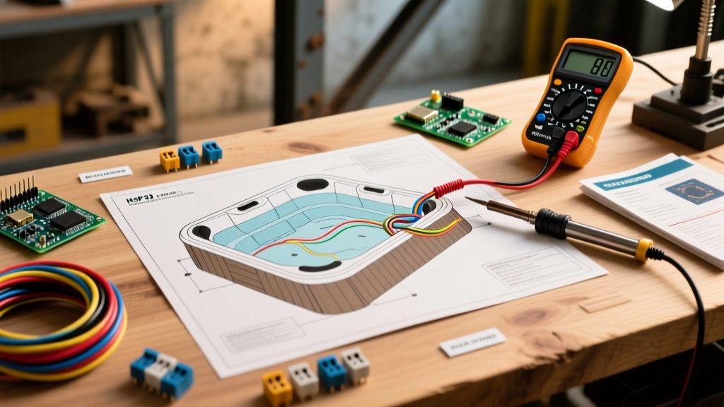

The Anatomy of a 240V Spa Circuit
When a modern hot tub—equipped with a digital spa pack like the Balboa BP501G1 or Gecko in.clear—fails to heat, trips the main breaker, or leaves the pump running on a single speed, guessing the problem is both dangerous and expensive. The hot tub electrical wiring diagram is your definitive roadmap. It translates the physical 6 AWG THHN copper wires and delicate 12V logic circuits into a traceable schematic. By understanding how to read this diagram, you can isolate faults to a specific $15 micro-switch rather than replacing a $400 main circuit board.
CRITICAL SAFETY WARNING: Hot tubs operate on 240V/50A circuits capable of delivering lethal current. All wiring and troubleshooting must comply with NEC Article 680. Always lock out and tag out the main 50A 2-pole GFCI breaker before opening the spa pack enclosure. Verify zero voltage with a CAT III multimeter before touching any terminals.Decoding the Diagram: Key Symbols and Components
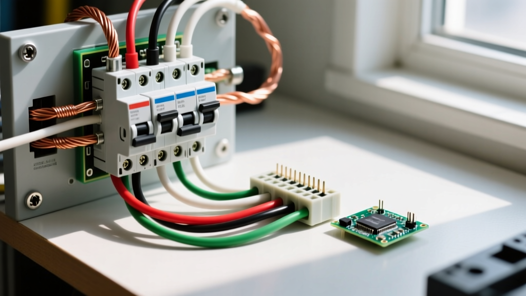
Before grabbing your multimeter, you must map the schematic symbols to the physical components inside the control box. Manufacturers use standardized electrical symbols, but spa-specific diagrams include unique representations for water safety devices.
| Schematic Symbol | Component Name | Real-World Example & Function |
|---|---|---|
| Zig-Zag Line | Heater Element | Inoxia 5.5kW Titanium Element. Converts electrical energy to heat. |
| Circle with 'M' | Pump Motor | Waterway Hi-Flo 2-Speed Pump. Circulates water for heating and jets. |
| Switch with Diagonal Line | Flow / Pressure Switch | Tecmark 4040-0001 Pressure Switch. Ensures water is moving before heating. |
| Rectangle with 'K' | Contactor / Relay | Definite Purpose Contactor. High-amperage switch controlled by low-voltage logic. |
| Thermometer Icon | High-Limit Sensor | 10k Ohm Thermistor. Shuts down heater if water exceeds 118°F (48°C). |
Step-by-Step Troubleshooting Using the Diagram
A wiring diagram is not just a map for installation; it is a sequential flowchart for troubleshooting. Let us break down the three most common hot tub electrical failures and how to trace them using the schematic.
Scenario 1: The 50A GFCI Breaker Trips Immediately
If the main subpanel GFCI breaker trips the moment you reset it, you have a ground fault or a neutral-to-ground bonding issue. Look at the hot tub electrical wiring diagram and trace the white neutral wire (Line N).
- The NEC Rule: According to the U.S. Consumer Product Safety Commission (CPSC) and NEC Article 680, the neutral wire must remain completely isolated from the equipment grounding conductor (EGC) at both the subpanel and the spa pack.
- The Trace: Follow the white neutral on the diagram. It should travel from the GFCI breaker, through the conduit, and terminate only at the spa pack's designated neutral bus bar. If you find the neutral bonded to the copper ground plate inside the spa pack, this is your fault.
- Component Isolation: If the neutral is correctly isolated, the fault lies in a component. Disconnect the 240V load wires (usually red and black) from the heater contactor and the pump relays one by one. Reset the breaker after each disconnection. When the breaker holds, the last disconnected component has an internal short to ground.
Scenario 2: Heater Not Engaging (No Heat)
The pump runs, the display shows 'Heating', but the water remains cold. The diagram reveals that the heater circuit is a series loop of safety switches that must all be closed to energize the heater contactor coil.
- Trace the Control Voltage: Locate the 240V (or 12V, depending on the board) line feeding the high-limit switch. Using your multimeter, verify voltage on the input side.
- Test the Flow/Pressure Switch: The diagram shows this switch in series immediately after the high-limit sensor. If the filter is clogged, water flow drops, the switch remains open, and the contactor never pulls in. Bypass the switch momentarily with a jumper wire only for testing. If the heater kicks on, clean your filters or replace the $18 pressure switch.
- Test the Contactor Coil: If voltage reaches the contactor coil (A1 and A2 terminals) but the contactor does not physically 'click' shut, the coil is burned out. Set your multimeter to Ohms; a healthy coil reads between 50Ω and 150Ω. An 'OL' (Open Line) reading means the contactor must be replaced.
- Test the Element: If the contactor clicks but the water stays cold, test the heater element. Disconnect power, remove the element wires, and measure resistance. A standard 5.5kW element at 240V should read exactly 10.5 ohms. A 4.0kW element reads 14.4 ohms. If it reads 'OL', the internal wire is broken, and you need a new titanium element.
Scenario 3: Pump Runs on Low Speed Only
Two-speed pumps utilize three hot terminals: Common (C), Low Speed (L), and High Speed (H). The hot tub electrical wiring diagram will show two separate relays on the main board—one for low, one for high. If the pump hums but won't shift to high speed, the high-speed relay on the board is likely fused shut or failed to engage. Swap the high and low relay trigger wires on the board; if the pump now runs on high when 'Low' is selected, the spa pack's high-speed relay is dead, requiring a $120 board repair or replacement.
Multimeter Testing Matrix for Spa Pack Terminals
Use this reference matrix when probing the main terminal blocks on a standard 240V/50A spa pack. Always verify your multimeter is rated for CAT III 600V minimum.
| Test Point | Multimeter Setting | Expected Reading (Healthy) | Troubleshooting Note |
|---|---|---|---|
| L1 to L2 (Main Input) | VAC (AC Voltage) | 240V (±10%) | If 120V, one leg of the subpanel breaker is tripped or a bus bar is burnt. |
| L1 to Neutral | VAC (AC Voltage) | 120V | Powers 120V accessories like the ozone generator or spa light. |
| Heater Element Terminals | Ohms (Ω) | 10.5Ω (5.5kW) or 14.4Ω (4kW) | Must be tested with power OFF and wires disconnected. |
| Heater Element to Ground | Ohms (Ω) | OL (Infinite Resistance) | Any reading other than OL indicates a grounded element causing GFCI trips. |
| Topside Panel 12V DC | VDC (DC Voltage) | 12V to 14V DC | Test the 4-pin or 7-pin AMP connector. 0V indicates a blown 5A board fuse. |
Common Wiring Mistakes in 4-Wire vs. 3-Wire Setups
One of the most frequent reasons a newly installed hot tub fails inspection or trips the GFCI is a misunderstanding of legacy 3-wire versus modern 4-wire diagrams.
'The most dangerous mistake I see in the field is DIYers adapting an old 3-wire 240V dryer circuit for a modern hot tub. Modern Balboa and Gecko spa controls require a dedicated 4-wire setup (two hots, one neutral, one ground). Tying the neutral to the ground at the spa pack to make a 3-wire circuit work will instantly trip a 50A GFCI breaker every single time.' — Master Electrician, NEC Code Consultant
Always ensure your conduit contains four individual THHN/THWN-2 conductors (Black, Red, White, Green) for a 240V setup. For runs exceeding 50 feet, upgrade from 6 AWG to 4 AWG copper to mitigate voltage drop, which can cause the spa pack's microprocessor to reset erratically during pump startup surges.
Frequently Asked Questions
Can I use a wiring diagram from a different spa pack model?
No. Even within the same brand, pinouts for the topside control panel, temperature sensor resistance curves (10k vs 50k thermistors), and relay logic vary wildly between models like the Balboa VS500Z and the BP501G1. Using the wrong diagram can send 240V into a 12V logic board, instantly destroying the microprocessor.
Why does my diagram show a 120V heater instead of 240V?
Some inflatable or plug-and-play 110V/120V hot tubs use 1kW to 1.5kW heaters. The wiring diagram for these units will show a single 120V hot leg, a neutral, and a ground, plugging into a standard 15A or 20A GFCI wall receptacle. The troubleshooting logic remains the same, but expected resistance values for a 1.5kW 120V element will be much lower (approx. 9.6 ohms).
Where can I find the specific diagram for my hot tub?
The exact hot tub electrical wiring diagram is almost always printed on the inside of the spa pack's plastic enclosure door. If it is faded or missing, locate the model and serial number on the main circuit board and download the technical service manual directly from the manufacturer's portal.