
Mastering the Wiring Diagram for Nest Thermostat Installations
Whether you are installing the latest Nest Learning Thermostat (4th Gen) or the standard Nest Thermostat, understanding the underlying HVAC control logic is critical. A smart thermostat is not merely a plug-and-play device; it acts as a complex relay controller that interfaces directly with your air handler's 24VAC control board. This comprehensive guide breaks down the exact wiring diagram for Nest thermostat setups, covering conventional systems, heat pumps, and the ubiquitous C-wire dilemma.
Critical Safety: Low Voltage vs. Line Voltage
Before touching a single wire, you must verify your system's voltage. Nest thermostats are designed exclusively for 24VAC low-voltage systems. They are fundamentally incompatible with 120V or 240V line-voltage systems, such as electric baseboard heaters or in-wall fan coils. Connecting line voltage to a Nest baseplate will instantly destroy the internal logic board and poses a severe fire hazard. If you have a line-voltage system, you must use a switching relay, such as the Aube TH106, to step down the control signal. Always shut off the 15A or 20A breaker at your main electrical panel and verify the 3A or 5A automotive-style fuse on your HVAC control board is intact before beginning.
Nest Baseplate Terminal Reference Chart
The Nest baseplate utilizes a standardized labeling system that aligns with traditional HVAC wiring colors, though physical wire colors in older homes are notoriously unreliable. Always label your existing wires based on the terminal they occupy on your old thermostat, not their insulation color.
| Terminal | Standard Wire Color | Function & System Role | Voltage / State |
|---|---|---|---|
| R / Rh / Rc | Red | 24VAC Power (Hot). Rc is for cooling power, Rh for heating. Nest internally bridges them if only one R wire is present. | 24VAC Constant |
| W1 | White | Stage 1 Heat. Energizes the gas valve or electric heat strip relay. | 24VAC Switched |
| W2 | Black/Blue | Stage 2 Heat or Emergency Heat (E/AUX). | 24VAC Switched |
| Y1 | Yellow | Stage 1 Cooling. Sends 24VAC to the outdoor condenser contactor coil. | 24VAC Switched |
| G | Green | Indoor Blower Fan. Energizes the fan relay independently of heating or cooling. | 24VAC Switched |
| C | Blue/Brown | Common Wire. Completes the 24VAC circuit to provide continuous power to the Nest. | 24VAC Return |
| O/B | Orange | Heat Pump Reversing Valve. O energizes in cool (Rheem), B energizes in heat (Carrier). | 24VAC Switched |
Diagram Logic 1: Standard Conventional HVAC (1H/1C)
For a standard forced-air gas furnace paired with a central air conditioner, the wiring diagram for your Nest thermostat requires a minimum of four wires, though five (including the C-wire) is the modern standard.
- R to R (or Rh): Provides the baseline 24VAC power from the transformer.
- W1 to W1: Triggers the furnace sequence (inducer motor, igniter, gas valve, blower).
- Y1 to Y1: Triggers the outdoor AC compressor and simultaneously signals the air handler to run the blower.
- G to G: Manual fan control.
- C to C: The common return path.
Pro-Tip: When stripping 18-gauge thermostat wire (18/5 or 18/8 AWG), strip exactly 1/4 inch to 3/8 inch of insulation. Inserting too much bare copper risks a short circuit against adjacent terminals, which will instantly blow the 3A fuse on your furnace control board.
Diagram Logic 2: Heat Pump Systems & The O/B Reversing Valve
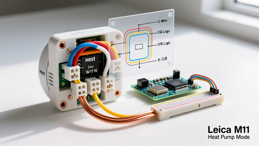
Heat pumps introduce a unique component to the wiring diagram for Nest thermostat configurations: the reversing valve. This valve dictates whether the system is heating or cooling by reversing the flow of refrigerant. The O/B terminal controls this valve, but the logic varies by manufacturer.
Brand-Specific O/B Logic:
Most manufacturers (Rheem, Ruud, Trane) energize the O terminal during the cooling cycle. Conversely, brands like Carrier, Bryant, and Lennox typically energize the B terminal during the heating cycle. The Nest thermostat handles this via a software toggle during setup (Settings > Equipment > Reversing Valve > O or B), meaning you only wire the single orange wire to the O/B terminal regardless of the brand.
If you have a dual-fuel system (a heat pump with a gas furnace backup), you will utilize the W2/AUX terminal to trigger the fossil fuel kit or the furnace control board when outdoor temperatures drop below your economic balance point (typically around 35 degrees Fahrenheit).
The C-Wire Dilemma: Power Stealing vs. Dedicated Common
The most common hurdle when referencing any smart thermostat wiring diagram is the absence of a C-wire (Common wire). The C-wire provides a continuous 24VAC return path to power the Nest's Wi-Fi radio, display, and sensors.
What is Power Stealing?
If you do not have a C-wire, the Nest attempts to steal power by passing a trickle of current (typically under 40mA) through the Y1 or W1 circuits when the HVAC system is off. This trickle charges an internal lithium-ion battery. However, power stealing can cause severe edge-case failures:
- Contactor Chatter: The trickle current can partially energize the outdoor AC contactor coil, causing it to rapidly click or hum without fully engaging the compressor.
- Ghost Cycling: Some high-efficiency furnaces with advanced control boards may interpret the trickle current as a legitimate call for heat, turning the blower on randomly.
The Nest Power Connector (G4-PWR) Solution
If running a new 18/5 cable from your air handler to the thermostat is impossible due to finished walls, the Nest Power Connector (G4-PWR) (retailing around $35) is the code-compliant alternative. This device wires directly into your air handler's 24VAC transformer (C and R terminals) and sends a modulated power signal over the existing thermostat wires to the Nest baseplate's C terminal, eliminating power stealing entirely.
Troubleshooting Matrix: Common Nest Wiring Errors
| Error Code | Meaning | Root Cause & Diagnostic Fix |
|---|---|---|
| N260 / N261 | No C-Wire Detected | The Nest cannot maintain a stable power draw. Install a C-wire or Nest Power Connector to stabilize the 24VAC circuit. |
| E73 | No Power to Rc | Loss of 24VAC. Check the main breaker, the condensate overflow float switch (which cuts power when full), and the 3A/5A blade fuse on the HVAC control board. |
| E74 | No Power to Rh | Similar to E73 but isolated to the heating transformer. Common in systems with separate heating and cooling air handlers. |
| Delayed Cooling (Flashing Blue) | Compressor Protection | Not a wiring error, but a software lockout. The Nest enforces a 5-minute delay after an AC cycle ends to prevent liquid slugging and short-cycling the compressor. |
NEC Compliance and Professional Best Practices
When modifying thermostat wiring, adherence to the National Electrical Code (NEC) is mandatory. Thermostat wiring falls under NEC Article 725 (Class 1, Class 2, and Class 3 Remote-Control, Signaling, and Power-Limited Circuits). Class 2 circuits (your standard 24VAC HVAC control) are inherently safe from fire initiation due to their low power limitations, but they must not be run in the same conduit or junction box as 120V/240V line-voltage wiring to prevent inductive interference and shock hazards.
Always use UL-listed 18 AWG solid copper thermostat wire. Avoid using stranded wire (like speaker wire or security wire), as the stranded ends can fray when inserted into the Nest's push-button terminals, leading to loose connections, voltage drops, and intermittent system failures. For comprehensive compatibility checks before purchasing, always cross-reference your specific HVAC control board model with the official Google Nest compatibility database.