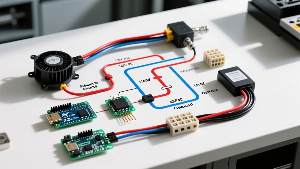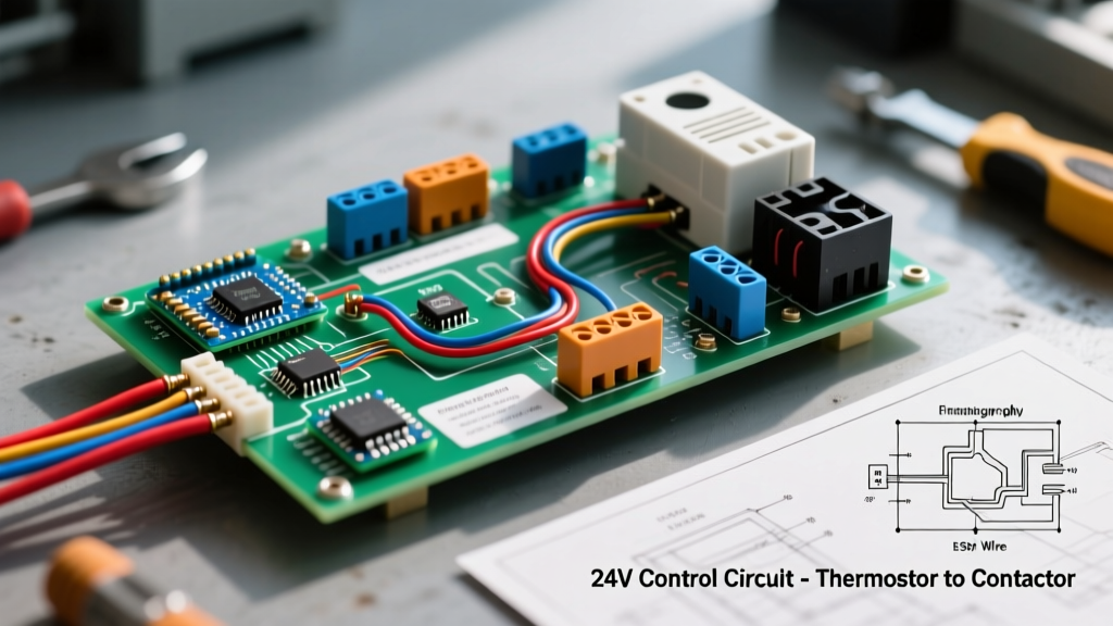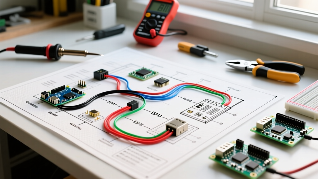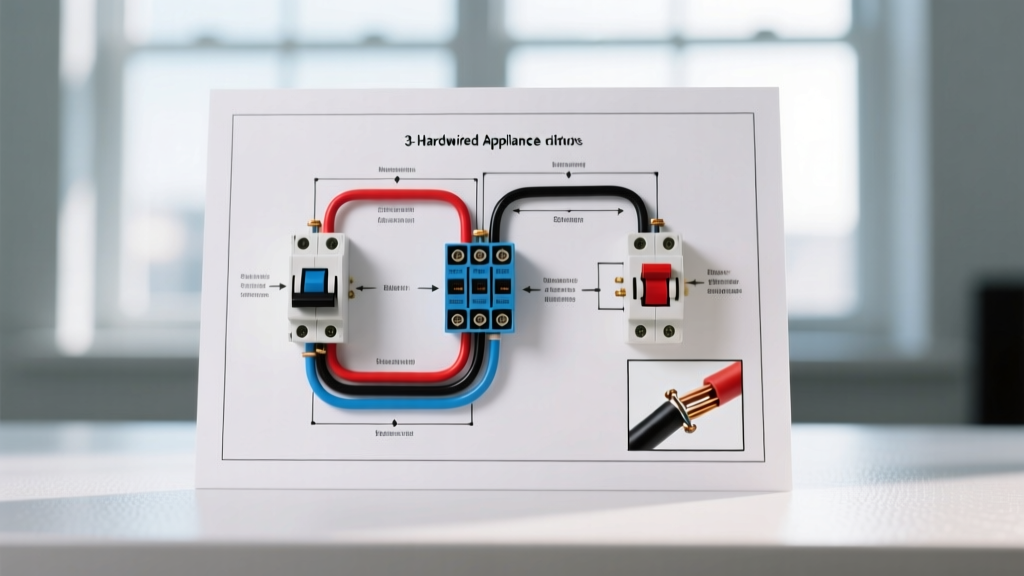

Why Standard Lighting Diagrams Fail on Appliance Motors
When most DIYers and apprentice electricians search for a 3 way electrical wiring diagram, the results almost exclusively focus on residential lighting circuits—hallways, staircases, and garages. But what happens when your project requires controlling a hardwired appliance motor from two different locations? Common examples include a 120V whole-house attic exhaust fan, a basement dehumidifier pump, a workshop dust collection system, or a hardwired air compressor.
Applying a standard lighting 3-way diagram directly to an appliance motor is a severe fire hazard. Standard 3-way switches (like the ubiquitous Leviton 5603) are rated for 15A resistive or tungsten loads. Appliance motors, however, are inductive loads. While a 1/2 HP attic fan might draw only 7 Amps under Full Load Amps (FLA), its Locked Rotor Amps (LRA) or inrush current during startup can spike to 35 Amps or more for a fraction of a second. This massive inrush current will rapidly pit, degrade, and eventually weld the internal contacts of a standard 15A lighting switch, leading to arcing, melted faceplates, and potential electrical fires.
The NEC Code Requirement: Separating Control from Power
To safely adapt a 3-way switching logic for an appliance, you must separate the control circuit from the power circuit. According to NFPA 70 (National Electrical Code), specifically Article 430.83 regarding Motor Controller Ratings, a switch used to control a motor must be rated for horsepower (HP) or be part of a listed motor controller assembly. Standard wall switches do not meet this requirement for most appliance motors.
The professional solution is to use the 3-way switches to control the low-current 120V coil of a Definite Purpose Contactor (DPC) or a heavy-duty relay, while the contactor's robust, motor-rated contacts handle the high-amperage 20A appliance circuit.
CRITICAL SAFETY WARNING: Never wire a hardwired motor appliance directly through standard residential wall switches. Always use a motor-rated contactor or a smart relay specifically rated for inductive motor loads (e.g., Shelly Plus 1 with a contactor addon) to manage the inrush current safely.
Bill of Materials: The Contactor-Based 3-Way Setup
Below is the exact hardware required to wire a 120V, 1/2 HP to 1 HP appliance motor from two locations safely. Pricing reflects average 2026 electrical supply costs.
| Component | Recommended Model | Specifications | Est. Cost |
|---|---|---|---|
| Definite Purpose Contactor | Eaton C25BND220 | 20A, 1-Pole, 120V AC Coil | $18.50 |
| 3-Way Switches (x2) | Leviton 5603 | 15A, 120V (Control Circuit Only) | $6.00 |
| Control Circuit Wire | Southwire 14/3 NM-B | 15A Max, Includes Ground | $0.45/ft |
| Power Circuit Wire | Southwire 12/2 NM-B | 20A Max, Includes Ground | $0.55/ft |
Step-by-Step Execution: Wiring the Dual-Circuit System
This setup requires two separate circuits originating from your main electrical panel: a 15A breaker for the switch control loop, and a 20A breaker for the appliance power feed. Both circuits must share a common neutral bar and grounding system.
Phase 1: Routing and Wiring the Control Circuit (15A)
The control circuit operates exactly like a standard 3 way electrical wiring diagram for lighting, but instead of sending power to a light fixture, it sends power to the contactor's electromagnetic coil.
- Power to Switch 1: Run 14/2 NM-B from the 15A breaker to the first 3-way switch location. Connect the black (hot) wire to the Common terminal (usually the dark-colored screw) on Switch 1. Connect the white (neutral) wire to the neutral wire nut in the box. Connect the bare ground to the green grounding screw.
- Travelers to Switch 2: Run 14/3 NM-B between Switch 1 and Switch 2. Connect the red and black wires to the two brass Traveler terminals on Switch 1. Connect the other ends to the brass Traveler terminals on Switch 2. Cap the white neutral wire in both boxes (it is not needed for the traveler run).
- Switch 2 to Contactor Coil: From the Common terminal on Switch 2, run a single black 14 AWG pigtail to the A1 terminal on the Eaton contactor coil.
- Completing the Coil Circuit: Run a white 14 AWG wire from the A2 terminal on the contactor coil and tie it into the main neutral wire bundle.
Phase 2: Wiring the Appliance Power Circuit (20A)
This is where the heavy lifting happens. The contactor acts as a bridge for the 20A appliance circuit, triggered by the 15A control circuit.
- Line Power to Contactor: Run 12/2 NM-B from the 20A breaker to the junction box housing the contactor. Connect the black (hot) wire to the L1 (Line) terminal on the contactor. Torque the terminal screw to the manufacturer's specification (typically 14-18 in-lbs for Eaton C25 series).
- Load to Appliance: Run 12/2 NM-B from the T1 (Load) terminal on the contactor directly to the hardwired appliance motor's hot terminal.
- Neutral Bypass: The contactor only switches the hot leg. Connect the white (neutral) wire from the 20A breaker directly to the appliance motor's neutral terminal using a wire nut. Do not route the neutral through the contactor.
- Equipment Grounding: Bond all bare copper ground wires together in the contactor junction box and connect a pigtail to the box itself (if metal) and to the appliance motor's ground terminal. Per the U.S. Department of Energy Electrical Wiring Guide, continuous equipment grounding is mandatory for all hardwired motor appliances to ensure fault current safely trips the breaker.
Troubleshooting Matrix: Common Appliance 3-Way Failures
When adapting lighting diagrams for motor appliances, unique failure modes emerge. Use this diagnostic matrix if your installation behaves erratically.
| Symptom | Root Cause | Expert Solution |
|---|---|---|
| Contactor hums loudly but fails to pull in the contacts. | Voltage drop on the 14 AWG control wire. The 120V coil is receiving less than 105V due to a long wire run. | If the control wire run exceeds 60 feet, upgrade the 14/3 NM-B control wire to 12/3 NM-B to reduce resistance and maintain coil voltage. |
| Appliance motor stutters or trips breaker on startup. | Contactor HP rating is insufficient for the specific motor's Locked Rotor Amps (LRA). | Verify the motor nameplate. If the motor is 1 HP or greater at 120V, upgrade to a 30A contactor (e.g., Eaton C25BND230) to handle the higher inrush current. |
| Switches feel warm to the touch after extended use. | Using standard residential dimmers or smart switches not rated for the inductive coil load of the contactor. | Ensure you are using standard, mechanical toggle or rocker 3-way switches. Inductive coil loads can destroy the TRIACs inside standard smart switches. |
Final Safety and Inspection Notes
Before energizing the system, perform a continuity test with a multimeter to ensure no short circuits exist between the hot and neutral lines, and verify that the equipment grounding conductor has a continuous, unbroken path back to the main panel's ground bus. When mounting the contactor, ensure it is housed in a proper NEMA-rated junction box or enclosure; contactors should never be left exposed in wall cavities due to the arc flash potential during contact separation.
By utilizing a contactor alongside your 3 way electrical wiring diagram, you bridge the gap between convenient dual-location control and strict NEC motor safety codes, ensuring your hardwired appliance operates reliably for decades without degrading your wall switches.