
The 2026 Standard: Why Precision Cat 6 Termination Matters
As residential and commercial networks upgrade to Wi-Fi 7 (802.11be) and multi-gigabit switches in 2026, the physical layer of your network is more critical than ever. A flawless Cat 6 wiring diagram for wall plates A or B is no longer just about getting a link light; it is about sustaining 10Gbps speeds over 55 meters and delivering stable PoE++ (Power over Ethernet) to high-draw access points. However, terminating the wall plate is only half the battle. For true network stability, your low-voltage structured wiring panel must be correctly integrated, grounded, and isolated from the high-voltage main breaker panel to prevent catastrophic Electromagnetic Interference (EMI).
In this comprehensive Panel & Breaker Guide, we dissect the exact termination steps for T568A and T568B wall plates, while providing crucial routing and grounding protocols for your central structured media enclosure. According to the BICSI Telecommunications Distribution Methods Manual, over 70% of network failures stem from poor physical layer termination and improper cable routing near power sources.
T568A vs T568B: Decoding the Wiring Standards
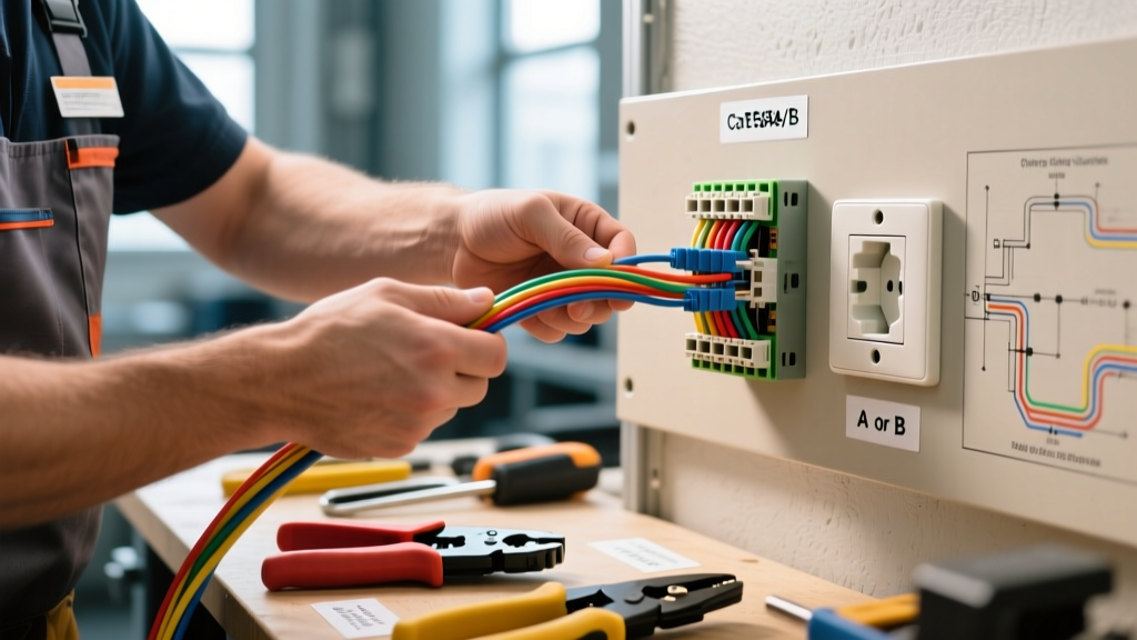
When searching for a Cat 6 wiring diagram for wall plates A or B, you will encounter two distinct color-code standards defined by the TIA-568.2-D specification. Both standards perform identically in terms of bandwidth and crosstalk cancellation, but mixing them on the same cable run will result in a split-pair failure, destroying your 10Gbps throughput.
Color Code Comparison Matrix
| Pin | T568A Color Code | T568B Color Code | Function (10GBASE-T) |
|---|---|---|---|
| 1 | White/Green | White/Orange | TX+ / BI_DA+ |
| 2 | Green | Orange | TX- / BI_DA- |
| 3 | White/Orange | White/Green | RX+ / BI_DB+ |
| 4 | Blue | Blue | BI_DC+ |
| 5 | White/Blue | White/Blue | BI_DC- |
| 6 | Orange | Green | RX- / BI_DB- |
| 7 | White/Brown | White/Brown | BI_DD+ |
| 8 | Brown | Brown | BI_DD- |
Which should you choose? In the United States, T568B is the de facto standard for residential and commercial deployments due to its backward compatibility with legacy AT&T/Bell System USOC wiring. T568A is strictly mandated for federal government contracts and is common in Canadian residential builds. The golden rule for 2026 structured cabling: pick one standard (usually B) and use it on both the wall plate keystone jack and the patch panel in your media enclosure.
Step-by-Step Keystone Jack Termination
Modern Cat 6 wall plates utilize 110-IDC (Insulation Displacement Contact) keystone jacks, such as the Leviton QuickPort or Panduit Mini-Com series. Do not use cheap, unshielded plastic jacks for multi-gig networks; the return loss will fail certification.
- Strip the Jacket: Use a precision stripping tool to remove exactly 1.5 inches of the outer PVC or Plenum jacket. Do not score the inner twisted pairs.
- Expose the Spline: Cat 6 cables feature a central plastic cross-spline to maintain pair separation. Trim the spline flush with the jacket edge.
- Untwist with Extreme Prejudice: Untwist the pairs only as far as necessary to seat them into the IDC slots. The TIA standard mandates that no more than 0.5 inches of any pair be untwisted. Exceeding this causes Near-End Crosstalk (NEXT) failures.
- Seat and Punch Down: Lay the wires into the color-coded slots matching your chosen T568B (or A) diagram. Using a calibrated punch-down tool (like the Klein Tools VDV226-110 set to the 'cut' side facing outward), press down firmly until you hear a distinct click, which simultaneously seats the wire and trims the excess.
- Secure the Cap: Snap the keystone retention cap over the termination block. This maintains the twist geometry and provides strain relief.
Structured Panel & Breaker Guide: Routing and EMI Avoidance
Terminating the wall plate correctly is useless if your cable run passes unshielded through a high-EMI zone. In most homes, the central structured wiring panel (e.g., a Leviton or OnQ metal enclosure) is mounted directly adjacent to, or sometimes inside the same stud bay as, the main AC electrical breaker panel. This is a massive hazard for 10Gbps Ethernet.
NEC Separation Requirements
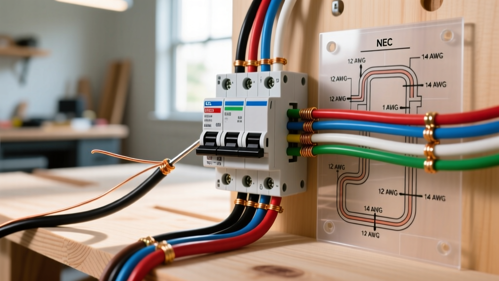
According to the National Electrical Code (NEC) Article 800.133, communications cables must maintain a strict physical separation from electric light or power conductors. For standard 120V/240V residential AC lines running parallel to your Cat 6, you must maintain a minimum 12-inch separation. If you must cross a high-voltage AC line, you must do so at a strict 90-degree angle to minimize inductive coupling.
Expert Warning: Never fish Cat 6 cable through the same conduit, knockouts, or stud holes as 120V Romex. The 60Hz magnetic field from the AC lines will induce low-frequency noise that destroys the Signal-to-Noise Ratio (SNR) required for 10GBASE-T modulation, resulting in constant link flapping at the switch.
Grounding the Structured Media Panel
Your low-voltage panel must be bonded to the electrical system's grounding electrode system. Run a minimum 6 AWG bare copper grounding wire from the structured media enclosure's grounding lug directly to the main breaker panel's ground bus bar. This provides a safe fault-current path and ensures that any shielded Cat 6A patch cables used inside the panel have a proper drain path, preventing ground loops that can fry switch ports during a lightning surge.
Common Failure Modes in Multi-Gig Networks
When troubleshooting a newly terminated Cat 6 run using a certifier like the Fluke Networks DSX-5000, technicians frequently encounter these specific edge cases:
- Split Pairs: Caused by mixing T568A on the patch panel and T568B on the wall plate. The cable will pass a basic continuity test (wiremap) but will fail catastrophically on NEXT and Alien Crosstalk tests because the balanced twisted-pair geometry is broken.
- Return Loss Failures: Often caused by using a Cat 5e keystone jack on a Cat 6 cable, or crushing the cable jacket with overly tight zip-ties in the media panel. Impedance mismatches cause signals to reflect back to the transmitter.
- PoE Voltage Drop: If running 802.3bt (PoE++ up to 90W) to a Wi-Fi 7 AP, cheap 24AWG CCA (Copper Clad Aluminum) cables will overheat and melt the keystone contacts. Always use 23AWG solid bare copper Cat 6.
Quick Reference: Cat 6 vs. Cat 6A for 2026 Panels
| Feature | Cat 6 (U/UTP) | Cat 6A (F/UTP or U/UTP) |
|---|---|---|
| Max 10Gbps Distance | 55 Meters (180 ft) | 100 Meters (328 ft) |
| Bandwidth | 250 MHz | 500 MHz |
| Alien Crosstalk (AXT) | Highly susceptible in bundled runs | Engineered to resist AXT |
| Panel Termination | Standard 110-IDC Keystone | Requires shielded die-cast jacks & grounding |
| Best 2026 Use Case | Single-family residential, short runs | Commercial, dense bundles, high-EMI zones |
For further validation testing and advanced troubleshooting methodologies, refer to the Fluke Networks Knowledge Base for whitepapers on Tier 1 vs Tier 2 certification testing.
Final Thoughts on Panel Integration
Mastering the Cat 6 wiring diagram for wall plates A or B is a foundational skill, but treating the wall plate as an isolated component is a rookie mistake. True network reliability in the multi-gigabit era requires a holistic view of the physical layer. By strictly adhering to T568B color codes, maintaining the 0.5-inch untwist limit, and rigorously enforcing NEC 800.133 separation distances from your main breaker panel, you will build a 2026-ready network infrastructure that delivers flawless 10Gbps throughput and stable PoE++ power delivery for years to come.