
Decoding the 48v Electric Scooter Wiring Diagram PDF
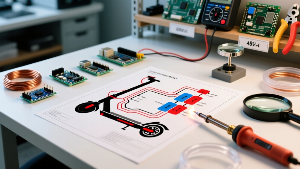
When builders and repair technicians search for a 48v electric scooter wiring diagram pdf, the immediate focus is usually on the motor controller, throttle potentiometer, or hall sensor pinouts. However, from a safety and electrical engineering perspective, the most critical section of that schematic is the breaker panel and overcurrent protection layout. A 48V nominal lithium-ion battery pack actually operates at 54.6V fully charged (assuming a 13S configuration) and can deliver catastrophic short-circuit currents exceeding 300 amps if a fault occurs.
Interpreting the panel section of your PDF diagram requires understanding the difference between high-current propulsion paths and low-current logic circuits. Standard schematics will route the main positive trunk from the battery's discharge port (C-) through a primary DC disconnect, into a busbar, and then to the motor controller's B+ terminal. Secondary branches will step down through accessory fuses to power lighting, horns, and displays. Getting this hierarchy wrong doesn't just risk a blown fuse; it risks a localized electrical fire.
The Golden Rule: Never Use AC Breakers for DC Panels
A common and highly dangerous mistake in DIY scooter builds is repurposing standard household AC circuit breakers for the main panel. Alternating Current (AC) naturally crosses zero volts 120 times a second (in a 60Hz system), which helps extinguish the electrical arc that forms when breaker contacts separate. Direct Current (DC) has no zero-crossing. If an AC breaker trips under a 54V DC load, the arc will sustain, melting the breaker housing and potentially welding the contacts shut, rendering the safety device useless.
Safety Directive: Always use breakers specifically rated for DC voltage and current. According to the Blue Sea Systems Circuit Protection Guide, DC breakers utilize specialized arc chutes and magnetic blowouts to physically force the arc into extinction. For a 48V scooter, ensure your breaker is rated for at least 65V DC.
DC Breaker and Wire Gauge Sizing Matrix
Your 48v electric scooter wiring diagram pdf will usually specify the motor wattage, but it rarely provides the nuanced engineering data required to size the panel components correctly. You must size the breaker to protect the wire, not the load. The wire gauge must be selected based on the continuous current draw of the motor controller, plus a 25% safety margin for thermal derating inside an enclosed scooter deck.
| Motor Wattage | Continuous Amps | Peak / Inrush Amps | Minimum Wire Gauge (AWG) | Recommended DC Breaker |
|---|---|---|---|---|
| 1000W | 25A | 45A | 8 AWG Silicone | 40A DC Magnetic |
| 1500W | 35A | 60A | 6 AWG Silicone | 60A DC Magnetic |
| 2000W | 45A | 85A | 4 AWG Silicone | 80A DC Magnetic |
| 3000W+ | 65A | 120A+ | 2 AWG Silicone | 120A Class T Fuse |
Note: For systems exceeding 2000W, magnetic-hydraulic breakers become physically large and expensive. At this tier, the PDF diagram will often specify a Class T fuse (like the Bussmann CNN series) paired with a heavy-duty manual disconnect switch rather than a standard toggle breaker.
Understanding Inrush Current and Pre-Charge Circuits
If your main breaker trips the exact millisecond you turn the scooter on, you are experiencing inrush current. Modern 48V motor controllers contain massive electrolytic capacitor banks. When the main breaker closes, these empty capacitors act as a dead short, pulling hundreds of amps for a fraction of a second. This spike can instantly trip a 60A breaker or weld the contacts of a cheap key switch.
Advanced wiring diagrams solve this with an anti-spark pre-charge circuit. This involves a secondary, smaller gauge wire with a high-wattage resistor (e.g., 150 ohms, 10W) that bypasses the main contactor. When you turn the key, the logic circuit engages the pre-charge resistor, slowly filling the capacitors over 1-2 seconds. Once voltage equalizes, the main heavy-duty relay closes. If your PDF lacks this, you must add an XT90-S anti-spark connector at the battery-to-panel junction.
2026 Smart BMS Panel Integration
In modern 2026 builds, the physical breaker panel is only half the equation. The Battery Management System (BMS) acts as a solid-state secondary breaker. High-end smart BMS units feature MOSFET arrays that can sever the discharge path in milliseconds if a short circuit is detected, long before a mechanical thermal breaker can react.
According to research on lithium-ion protection topologies published by Battery University, relying solely on a BMS for overcurrent protection is insufficient due to the risk of MOSFET failure in the 'closed' state. Therefore, your panel must feature a mechanical DC breaker as the primary fail-safe, with the BMS acting as the fast-acting secondary layer. When reading your schematic, ensure the BMS 'P-' (Discharge) pad is wired directly to the main negative busbar, bypassing any secondary switches that could cause logic faults.
Step-by-Step Physical Panel Assembly
Translating the 2D PDF diagram into a physical 3D panel requires strict adherence to vibration and thermal management protocols. Scooters endure immense high-frequency vibration, which will loosen standard screw terminals and cause arcing.
- Busbar Mounting: Use a tinned copper busbar (e.g., Blue Sea 4-stud) mounted on a non-conductive, fire-retardant base like Garolite (G10). Never mount busbars directly to the aluminum scooter deck without isolation standoffs.
- Terminal Crimping: Strip 105°C rated silicone stranded wire using a precision stripper. Use a closed-barrel hex crimp tool (like the Knipex KN974961) for all ring terminals. Soldering high-current DC connections is prohibited, as solder can melt and flow away from the joint under sustained thermal load.
- Breaker Installation: Mount the main DC breaker in an accessible, waterproof enclosure (IP65 rated minimum). Route the incoming positive from the XT90 connector directly to the breaker's 'Line' side, and the 'Load' side to the busbar.
- Accessory Fusing: Tap into the main busbar using an ATO/ATC fused block for 12V accessories. You must use a DC-DC step-down converter (buck converter) rated for at least 10A to drop the 54.6V battery voltage down to a stable 12V for lights and horns.
Edge Case Troubleshooting: Nuisance Tripping and Voltage Drop
Even with a perfect interpretation of the 48v electric scooter wiring diagram pdf, builders frequently encounter panel issues. The most common is nuisance tripping under heavy hill climbs. This occurs when the continuous rating of the breaker is too close to the controller's phase current limit. Always ensure your breaker's continuous rating is at least 15% higher than the controller's programmed battery current limit.
Another silent failure mode is voltage drop across the breaker. A healthy DC breaker should exhibit less than a 15mV drop at full load. If your scooter bogs down under acceleration, use a digital multimeter to measure the voltage directly at the battery terminals, and then at the controller's B+ terminal while the motor is loaded. If you see a discrepancy greater than 0.5V, your breaker contacts are oxidized, your crimps are loose, or your wire gauge is undersized. Replace the compromised component immediately to prevent thermal runaway.