
Decoding the Electrical Nervous System of the YFM350X
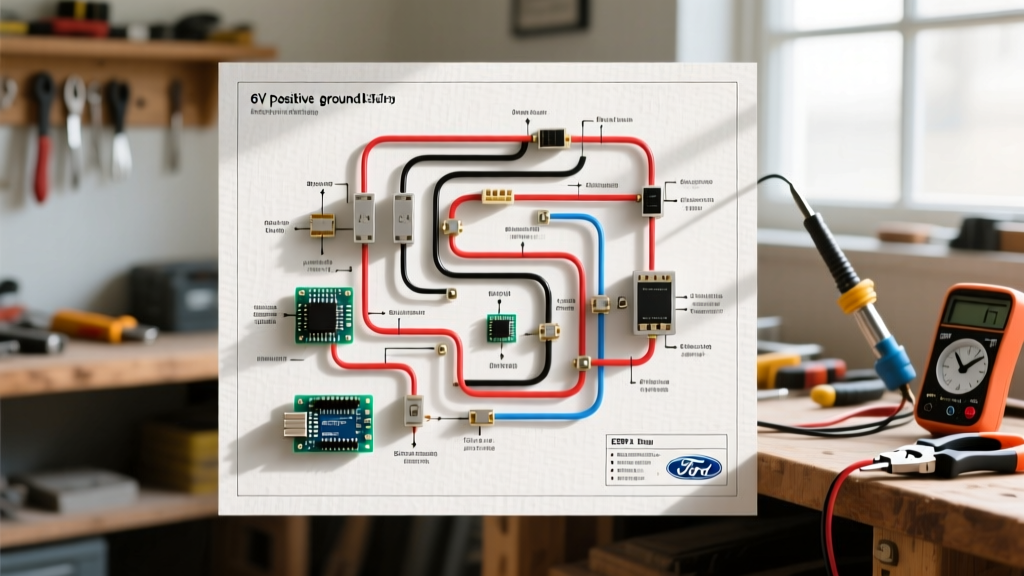
The Yamaha Warrior 350 (YFM350X) remains one of the most iconic 2WD sport ATVs ever produced. Manufactured between 1987 and 2004, thousands of these machines are still tearing up trails and farms today. However, after two decades of exposure to mud, water, and vibration, the electrical harness becomes a primary point of failure. When your Warrior refuses to start, lacks spark, or blows fuses, guessing is a waste of time and money. You need a systematic approach using a wiring diagram for Yamaha Warrior 350 models to isolate the fault.
In this comprehensive guide, we move beyond basic parts-swapping. We will break down the YFM350X schematic, provide exact multimeter resistance specifications, and outline step-by-step diagnostic flows for the most common electrical failures encountered in 2026.
Understanding Yamaha's Color-Coded Schematic Logic
Before probing a single connector, you must understand how Yamaha structures its official service manual schematics. Unlike automotive wiring, which often uses complex alphanumeric tracer codes, Yamaha ATV diagrams rely on primary and secondary wire colors.
- Red: Unswitched battery positive (12V DC).
- Black: Main chassis ground.
- White/Red & White/Green: Stator source coil and pickup coil signals.
- Yellow: AC output from the stator lighting coil (goes to the voltage regulator/rectifier).
- Orange: Ignition power / CDI trigger lines.
- Black/White: Engine kill switch and ignition ground-out circuit.
Pro-Tip for Aging Harnesses: On a 20+ year old Warrior 350, UV exposure and heat often fade Red wires to Pink, and Black wires to dark Grey. Always verify continuity to the battery terminals or chassis ground rather than trusting the insulation color alone.
Critical YFM350X Resistance Specifications
The most effective way to use the wiring diagram is to test the components at their connector pins. Below is the definitive diagnostic matrix for the Warrior 350's ignition and charging systems. Ensure your digital multimeter is zeroed before testing. For accurate micro-ohm readings on the stator, we recommend a high-quality meter like the Fluke 87V or 115 series to avoid false open-circuit readings.
| Component | Wire Colors (at Connector) | Expected Resistance (at 68°F/20°C) | Common Failure Symptom |
|---|---|---|---|
| Source Coil (Stator) | White/Red to White/Green | 0.40 - 0.55 Ω | No spark, hard starting when hot |
| Lighting Coil (Stator) | Yellow to Black (Ground) | 0.35 - 0.50 Ω | Dim headlights, dead battery |
| Pickup Coil (Pulser) | White/Red to White/Black | 145 - 195 Ω | Intermittent misfire, backfiring |
| Ignition Coil (Primary) | Orange to Black | 0.35 - 0.45 Ω | Weak spark, fouling plugs |
| Ignition Coil (Secondary) | Spark Plug Cap to Black | 7,000 - 10,500 Ω | Spark blows out under load |
Top 3 Electrical Faults & Diagram-Traced Solutions
1. The 'No Spark' Kill Switch Short
The most frequent cause of a sudden 'no spark' condition on the Warrior 350 is not a dead CDI, but a shorted kill switch or neutral safety switch. According to the wiring diagram, the Black/White wire runs from the CDI unit, through the handlebar kill switch, and down to the neutral safety switch on the engine case. If any part of this circuit grounds to the chassis, the CDI kills the ignition.
- Locate the CDI unit under the front fender/plastics.
- Disconnect the main CDI harness plug.
- Set your multimeter to continuity (ohms).
- Probe the Black/White pin on the harness side and a clean chassis ground.
- Diagnosis: If you have continuity (near 0 Ω) while the key is ON and the kill switch is in the 'RUN' position, you have a short. Inspect the handlebar switch housing for moisture corrosion and check the neutral switch wire near the shift drum for rubbed-through insulation.
2. Starter Relay Clicks But Engine Won't Turn
When you press the starter button, you hear a distinct 'click' from the relay under the seat, but the starter motor doesn't engage. The wiring diagram shows the starter circuit passes through the neutral safety switch and the brake light switch (on later models).
The Bypass Test: Use a heavy-gauge jumper wire to bridge the two large terminals on the starter relay. If the engine cranks, your starter motor and battery cables are fine. The fault lies in the low-amperage trigger circuit. Check the Sky Blue wire (starter button) and the Black/Yellow wire (neutral switch). Many previous owners bypass the neutral safety switch by splicing these wires together; if that hidden splice corrodes, the circuit fails.
3. Stator Burnout and AC Voltage Drops
If your battery constantly dies and the headlights pulse erratically at idle, your stator's lighting coil or the voltage regulator/rectifier (RR) is failing. Reference the diagram to find the Yellow wire exiting the stator case.
- Start the ATV and let it idle.
- Set your multimeter to AC Voltage (VAC).
- Probe the Yellow wire at the RR connector and chassis ground.
- Specification: You should see 18V to 24V AC at idle, rising to 40V+ AC at 5,000 RPM.
- If voltage is low, shut off the engine and test the stator resistance (see table above). If resistance is infinite (open loop), the stator is burned out and requires replacement.
2026 Replacement Parts & Repair Economics
When the wiring diagram confirms a dead component, you must decide between OEM and aftermarket replacements. While OEM Yamaha parts guarantee fitment, the aftermarket has vastly improved its stator and CDI offerings for the YFM350X platform. Below is a realistic pricing and reliability breakdown for 2026.
| Component | OEM Yamaha (Approx. Cost) | Premium Aftermarket (e.g., RM Stator, Moose) | Expert Recommendation |
|---|---|---|---|
| CDI Unit | $190 - $230 | $65 - $95 | Buy OEM. Aftermarket CDIs often alter the timing curve, causing top-end power loss on the 350. |
| Stator Assembly | $280 - $340 (Often NLA) | $75 - $110 | Buy Aftermarket. OEM stators are frequently discontinued (NLA) or overpriced for a 20-year-old design. |
| Regulator/Rectifier | $85 - $115 | $35 - $55 | Buy Aftermarket (MOSFET upgrade). Upgrading to a MOSFET RR runs cooler and saves the stator. |
| Main Wiring Harness | $350+ (If available) | N/A | Repair OEM. Use adhesive-lined heat shrink and OEM Yamaha connectors to rebuild brittle sections. |
Harness Repair: Soldering vs. Crimping in Off-Road Environments
When your diagnostic trace reveals a broken wire deep inside the harness loom, how you repair it dictates whether the fix lasts a week or a decade. The vibration profile of a single-cylinder 350cc engine is brutal on rigid connections.
The 'Western Union' Splice Protocol
Never use butt-crimps on low-voltage, low-amperage signal wires (like the pickup coil or CDI triggers). The mechanical stress will snap the wire adjacent to the crimp barrel. Instead, use the Western Union (Lineman's) splice:
- Strip 1.5 inches of insulation from both wire ends.
- Cross the wires and twist them tightly around each other (at least 4 full twists per side).
- Solder the joint using 60/40 rosin-core solder. Ensure the solder wicks fully into the strands.
- Seal with dual-wall adhesive-lined heat shrink. When heated, the inner meltable adhesive seals out moisture, preventing the green copper oxide corrosion that plagues ATV harnesses.
Information Gain - The Dielectric Grease Myth: Do not pack dielectric grease inside the pin cavity of a weatherpack connector. Dielectric grease is an insulator. It should only be applied to the outer rubber gasket seal of the connector to prevent water ingress and ease future removal. Packing it onto the metal pins can cause high-resistance voltage drops in 12V circuits.