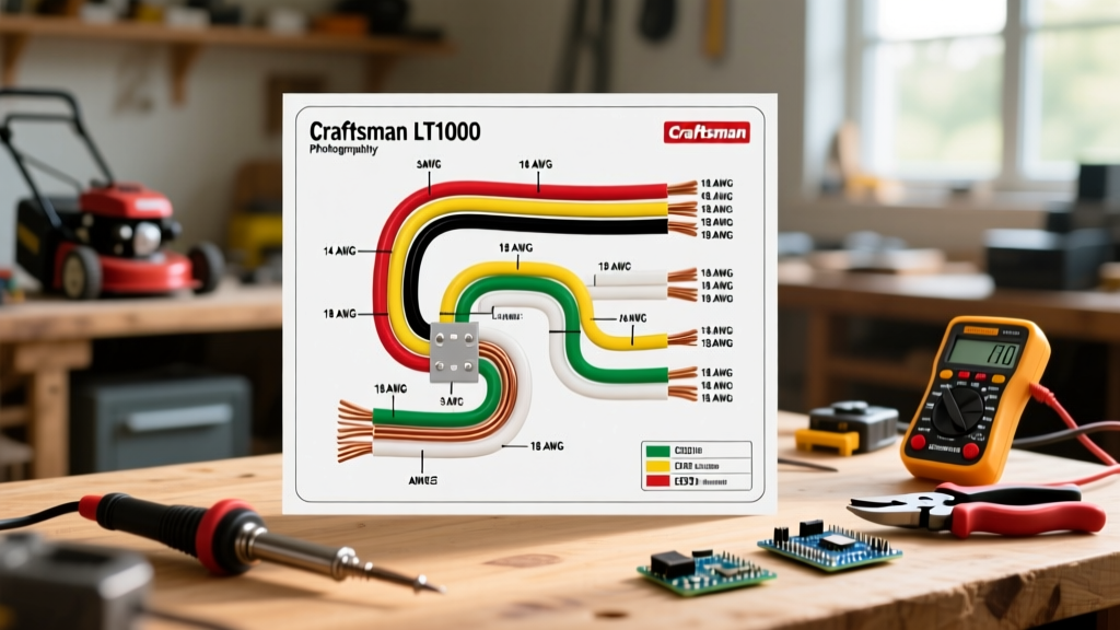

Decoding the Electrical System of the Craftsman LT1000
The Craftsman LT1000 remains one of the most popular lawn tractors ever produced, but its 12V DC electrical system can be a source of frustration when components fail. Whether you are replacing a corroded ignition switch, upgrading the stator, or bypassing a faulty safety interlock, relying on memory is a recipe for a short circuit. Understanding the wiring diagram for Craftsman LT1000 models requires more than just tracing lines; it demands a firm grasp of SAE standard wire color codes and precise American Wire Gauge (AWG) selection.
In this comprehensive guide, we break down the exact color coding used in the LT1000 harness, provide a master reference chart for wire gauge selection, and detail the most common failure modes specific to this chassis. As of 2026, sourcing OEM harnesses has become more expensive (typically ranging from $65 to $110), making targeted, wire-level repairs a highly cost-effective skill for DIY mechanics.
How to Read the Wiring Diagram for Craftsman LT1000
The factory service manual schematic for the LT1000 uses standardized electrical symbols. Before cutting or splicing any wire, you must understand the flow of current from the 12Ah Sealed Lead Acid (SLA) battery through the 30-amp main fuse, into the ignition switch, and out to the respective accessories.
Expert Tip: Never rely solely on wire color when diagnosing a used LT1000. Previous owners frequently replace damaged sections with whatever wire they have on hand. Always verify continuity with a digital multimeter (DMM) against the schematic.
The diagram is generally divided into three distinct sub-circuits:
- The Cranking Circuit: High-amperage path from the battery to the starter solenoid and starter motor.
- The Charging Circuit: Alternating current (AC) from the engine stator to the rectifier/voltage regulator, converting to DC to recharge the battery.
- The Accessory & Interlock Circuit: Low-amperage paths controlling the PTO clutch, headlights, and safety kill switches (seat, brake, and PTO engagement).
Craftsman LT1000 Wire Color Code Master Chart
The LT1000 wiring harness adheres closely to the SAE J1128 standard for low-tension primary cable, which is the benchmark for automotive and small engine 12V DC systems. Below is the definitive color code reference for the LT1000 platform.
| Wire Color | Primary Function | Typical Circuit / Component | Voltage State |
|---|---|---|---|
| Red | Battery Positive (B+) | Battery to Solenoid, Solenoid to Ignition Switch | Constant 12V DC |
| Black | Ground / Engine Kill | Battery Negative to Chassis, Ignition Coil Kill Wire | 0V (Ground) |
| Yellow | Stator AC Output | Stator to Voltage Regulator / Rectifier | 28V - 36V AC (RPM dependent) |
| White | Regulated DC Output | Voltage Regulator to Battery / Ignition Switch | ~13.8V - 14.4V DC |
| Purple | Ignition / Run Power | Ignition Switch to PTO Clutch, Fuel Solenoid | 12V DC (Key in RUN/START) |
| Green | Lighting / Accessories | Ignition Switch to Headlights, Taillights | 12V DC (Switch activated) |
| Orange / Blue | Safety Interlocks | Seat Switch, Brake Pedal Switch, PTO Switch | Logic Ground / 12V Interrupt |
The Safety Interlock System Logic
The LT1000 uses a complex interlock module to prevent the engine from cranking unless the brake is depressed and the PTO is disengaged. Furthermore, the engine will shut off if the operator leaves the seat while the PTO is engaged. The orange and blue wires typically carry the logic signals to the interlock relay. If your mower cranks but immediately dies when you release the brake, the fault is almost always a misadjusted brake switch or a broken blue logic wire near the pedal pivot.
Selecting the Correct Wire Gauge for LT1000 Repairs
Using the wrong wire gauge is the leading cause of electrical fires and premature component failure in riding mowers. The electromagnetic PTO clutch on the LT1000 draws between 3 to 5 amps upon engagement. If you use a wire gauge that is too thin, voltage drop occurs. A PTO clutch operating at 10V instead of 12V will slip, generate excessive heat, and eventually burn out the internal coil—a replacement cost of $120 to $180.
Refer to the BoatUS 12V DC wiring guidelines (which apply identically to 12V mower systems) for length-based voltage drop calculations. For the short runs found on an LT1000, the following AWG chart is your definitive guide.
| Circuit / Component | Max Current Draw | Minimum AWG Required | Recommended Insulation Type |
|---|---|---|---|
| Battery to Starter Solenoid | 150A+ (Surge) | 8 AWG or 6 AWG | XLPE or Heavy-Duty PVC |
| Solenoid to Ignition Switch (Main Feed) | 30A (Fused) | 10 AWG | GXL / TXL (Cross-linked) |
| PTO Electromagnetic Clutch | 5A | 14 AWG | GXL / TXL |
| Headlights / Taillights | 4A - 8A | 16 AWG | Standard PVC or GXL |
| Safety Switches / Interlock Logic | < 1A | 18 AWG | Standard PVC |
| Stator to Rectifier (AC) | 10A - 15A AC | 14 AWG (Stranded) | High-Temp Silicone or XLPE |
Why Insulation Type Matters in 2026
When purchasing replacement wire, avoid cheap, generic PVC wire for any circuit routed near the engine block or exhaust manifold. Modern DIY best practices dictate using GXL or TXL cross-linked polyethylene (XLPE) wire. These insulation types have a much thinner wall (allowing for easier routing through tight harness looms) and can withstand continuous temperatures up to 125°C (257°F), compared to standard PVC which becomes brittle and melts at much lower temperatures.
Step-by-Step: Tracing a Dead Battery Circuit Using the Diagram
If your LT1000 battery is constantly dying, the Briggs & Stratton charging system diagnostics recommend a systematic approach using the wiring diagram to isolate the fault.
- Verify Battery Health: Load test the 12V SLA battery. It must hold at least 9.6V under load for 15 seconds.
- Check the Stator (Yellow Wires): Unplug the stator connector. Set your DMM to AC Volts. Start the engine and run at full throttle. You should read between 28V and 36V AC across the two yellow wires. If you read 0V, the stator is dead or the flywheel magnets have detached.
- Check the Rectifier Output (White Wire): Reconnect the stator. Set the DMM to DC Volts. Probe the white wire output from the rectifier to ground. At full throttle, you must see 13.8V to 14.4V DC.
- Trace the Voltage Drop: If the rectifier outputs 14.2V, but the battery terminals only read 12.8V while running, you have high resistance in the white wire path. Check the inline fuse holder (often hidden under the dash) for corrosion, and inspect the spade connector at the ignition switch.
Common LT1000 Wiring Failure Modes & Edge Cases
Through years of field repairs, specific edge cases and failure points have emerged as notorious on the LT1000 chassis:
- The Steering Column Chafe Zone: The main harness is zip-tied along the frame rail, passing directly beneath the steering shaft. Over time, vibration and steering input cause the shaft to wear through the harness loom, eventually shorting the purple ignition wire to the black ground. Fix: Reroute the harness using split-loom tubing and adhesive-backed P-clips away from the steering column.
- PTO Clutch Connector Corrosion: The two-pin connector leading to the PTO clutch sits low on the chassis, directly in the path of thrown grass clippings and moisture. The pins corrode, increasing resistance and causing the clutch to slip. Fix: Clean with electrical contact cleaner and pack the connector cavity with dielectric grease.
- Aftermarket Seat Switch Bypasses: Many owners attempt to bypass the seat safety switch by jumping the orange wires. If done incorrectly (e.g., jumping the wrong pins on the 4-pin connector), it can feed 12V directly into the interlock module's ground path, instantly frying the module. Always consult the schematic before attempting a bypass.
Sourcing OEM vs. Universal Wiring Components
While you can purchase a complete OEM replacement harness from Sears PartsDirect or authorized dealers (Part numbers vary by exact LT1000 model year, often starting with 532 13 04-11), it is rarely necessary to replace the entire harness. In 90% of cases, the damage is localized.
Invest in a high-quality automotive wire crimper (avoid cheap plier-style crimpers) and a kit of heat-shrink butt connectors with adhesive lining. For the ignition switch itself, universal 4-position or 5-position mower switches (priced between $15 and $25) are widely available and can be wired in using the color code chart above, provided you map the terminal letters (B, L, A, S, G) correctly to the LT1000 schematic.
Frequently Asked Questions (FAQ)
What size is the main fuse on a Craftsman LT1000?
The LT1000 utilizes a standard 30-amp inline blade fuse (ATO/ATC style) located on the red wire between the starter solenoid and the ignition switch. Never replace this with a higher amperage fuse, as it protects the 14 AWG and 12 AWG wiring from catching fire in the event of a dead short.
Can I use automotive wire instead of mower-specific wire?
Yes. Automotive GXL or TXL primary wire meets and exceeds the requirements for small engine 12V DC systems. The SAE J1128 standard applies to both. Just ensure you are using stranded copper wire, never solid core, as the vibration of the mower will quickly snap solid core wire.
Why does my LT1000 backfire when I turn the key off?
This is often caused by a failing anti-afterfire solenoid on the carburetor bowl. The solenoid is powered by the purple (ignition/run) wire. If the ignition switch has internal resistance or the purple wire has voltage drop, the solenoid may not retract fully when the key is turned off, allowing unburned fuel to enter the hot muffler and ignite.