
The Electrical Anatomy of Modern Gas Fireplaces
When homeowners search for a wiring diagram for gas fireplace setups, they often confuse the low-voltage thermostat wiring with the critical line-voltage circuit required to power the unit. Modern direct-vent gas fireplaces, such as the Heat & Glo SL-7X series or Napoleon Ascent models, rely on sophisticated Intermittent Pilot Ignition (IPI) modules and high-CFM blower assemblies. These components demand a clean, dedicated 120V AC supply directly from your main electrical panel.
Unlike older standing-pilot systems that generated their own millivolt power via a thermopile, modern IPI systems utilize a step-down transformer to convert 120V AC to 6V DC. This powers the SIT Proflame 2 gas valve and the spark igniter. If the line-voltage circuit is undersized, poorly grounded, or sharing a neutral with other high-draw appliances, the IPI module will fail to open the gas valve, resulting in a cold hearth and locked-out error codes. This guide focuses strictly on the panel-to-fireplace line-voltage wiring diagram, ensuring your breaker sizing, wire gauge, and NEC compliance are up to 2026 standards.
Line Voltage vs. Low Voltage: Knowing the Difference
Before opening your electrical panel, it is vital to delineate the two distinct wiring systems in a gas fireplace:
- Line Voltage (120V AC): This is the primary power feed originating from your breaker panel. It supplies the internal transformer, the blower motor, and any integrated halogen or LED ember bed lighting. This requires standard NM-B (Romex) cable, a dedicated breaker, and strict adherence to NEC panel codes.
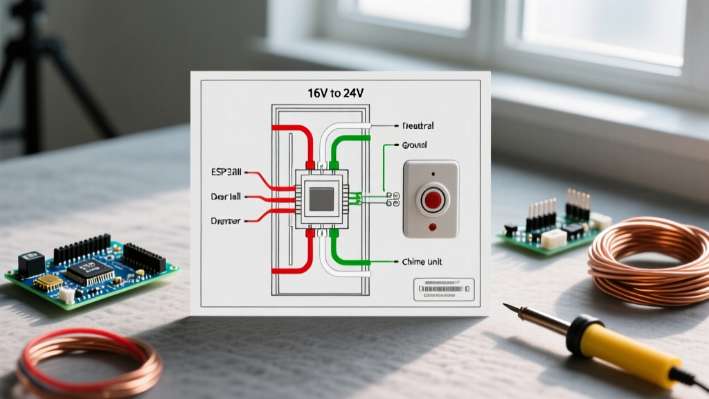
- Low Voltage (6V DC / Millivolt): This wiring is entirely contained within the fireplace chassis or runs to a wall-mounted remote control receiver and thermostat. It uses 18 AWG or 20 AWG low-voltage wire. Never connect low-voltage thermostat wires to line-voltage panel terminals.
Breaker Sizing and Wire Gauge Matrix
Selecting the correct breaker and wire gauge depends on the total amperage draw of your specific fireplace model. While the IPI ignition module draws less than 1 Amp, the blower motor and lighting accessories can push the total load higher. Below is the standard sizing matrix for residential gas fireplaces in 2026.
| Circuit Size | Wire Gauge (NM-B) | Max Continuous Load | Typical Application |
|---|---|---|---|
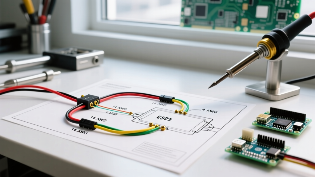
| 15 Amp | 14/2 AWG | 1,440 Watts (12A) | IPI Module + Standard Blower (No heavy lighting) |
| 20 Amp | 12/2 AWG | 1,920 Watts (16A) | IPI Module + High-CFM Blower + LED/Ember Lighting |
Expert Recommendation: Even if your current fireplace manual specifies a 15A circuit, running a 20A circuit with 12/2 NM-B cable is highly recommended. The material cost difference is roughly $0.25 per foot, but it future-proofs the circuit for aftermarket high-output blowers or electric ignition upgrades. A 20A Square D Homeline breaker (model HOM120) costs approximately $12 at major hardware retailers, while a 15A AFCI version (HOM115AFIC) runs about $38.
NEC 2026 Code Requirements: AFCI, GFCI, and Clearances
Electrical codes governing gas fireplace circuits have evolved significantly. When planning your wiring diagram for gas fireplace installations, you must adhere to the latest National Electrical Code (NEC) guidelines enforced by your local Authority Having Jurisdiction (AHJ).
AFCI Protection is Mandatory
Per NEC Article 210.12, all 120V, single-phase, 15- and 20-amp branch circuits supplying outlets in living rooms, family rooms, and recreation rooms must be protected by an Arc-Fault Circuit Interrupter (AFCI). Because your gas fireplace is hardwired or plugged into a receptacle in these living spaces, the breaker in your main panel must be a Combination-Type AFCI breaker. Standard thermal-magnetic breakers will fail inspection.
The GFCI Nuisance Tripping Hazard
A common point of confusion is whether a Ground-Fault Circuit Interrupter (GFCI) is required. Unless the fireplace receptacle is installed within 6 feet of a wet bar, kitchen sink, or an outdoor patio hearth, GFCI protection is generally not mandated by the NEC for living room fireplaces. Furthermore, gas fireplace transformers (especially older or heavily loaded SIT valves) can produce minor leakage currents and high inrush spikes during ignition. Installing a GFCI breaker or receptacle often results in nuisance tripping exactly when the fireplace attempts to ignite, leaving you without heat. Stick to AFCI protection unless your local code explicitly demands GFCI for hearth areas.
Physical Clearance from Flue Pipes
According to NFPA safety standards and NFPA 211 (Standard for Chimneys, Fireplaces, Vents, and Solid Fuel-Burning Appliances), NM-B electrical wiring must maintain a minimum clearance of 2 inches from any Class A chimney flue pipe or hot metal venting. If your wiring diagram routes the cable through the same stud bay as the direct-vent exhaust, you must install physical fire-blocking and maintain this air space to prevent the insulation jacket of the wire from melting.
Step-by-Step Panel to Fireplace Wiring Diagram
Follow this precise sequence to wire the line-voltage circuit from your main service panel to the fireplace junction box. Always verify local permitting requirements before beginning panel work.
- Main Power Shutoff: Turn off the main breaker to de-energize the panel bus bars. Use a non-contact voltage tester to confirm the bus bars are dead before touching any internal components.
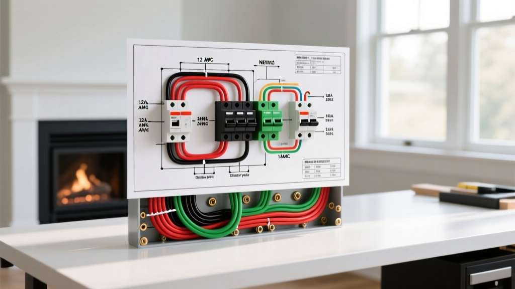
- Breaker Installation: Snap a 15A or 20A Combination AFCI breaker (e.g., Eaton BR115AF or Square D HOM115AFIC) into the appropriate slot on the bus bar. Connect the white neutral pigtail from the breaker directly to the panel's neutral bar.
- Cable Routing: Feed the 14/2 or 12/2 NM-B cable through a knockout in the panel using a proper Romex connector. Route the cable through the wall cavities to the fireplace location. Maintain the 2-inch clearance from the metal vent pipe.
- Fireplace Junction Box Termination: Most modern fireplaces, including those detailed in Heat & Glo installation manuals, feature a pre-installed metal junction box on the lower right or left side of the chassis. Strip the NM-B sheath and secure the cable with a cable clamp.
- Wire Connections:
- Black (Hot): Connect to the black line-voltage wire leading to the fireplace's internal transformer and blower switch.
- White (Neutral): Connect to the white neutral wire bundle using a wire nut or Wago lever connector.
- Bare (Ground): Connect to the green ground screw inside the metal junction box. Do not skip the ground. The IPI module requires a true earth ground to properly sense the pilot flame via flame rectification. An ungrounded system will spark endlessly but fail to open the main gas valve.
- Wall Switch Integration (Optional): If your wiring diagram includes a wall switch to control the fireplace, you must route a 14/2 switch loop from the junction box to the wall switch. The switch interrupts the hot leg going to the IPI module's 'TH' (Thermostat) terminal, not the main transformer power.
Expert Troubleshooting: Inrush Current and Failure Modes
Even with a perfect wiring diagram for gas fireplace setups, electrical anomalies can occur. Here is how to diagnose the most common panel and breaker-related failures:
AFCI Breaker Trips During Ignition
When the IPI module sparks, it creates high-frequency electrical noise. Older generation AFCI breakers sometimes misinterpret this arc signature as a dangerous parallel arc fault and trip. Solution: Upgrade to a newer generation AFCI breaker (2024-2026 models feature advanced digital signal processing that filters out appliance ignition noise). If the problem persists, consult the manufacturer; some require a specific line-noise filter installed at the junction box.
Voltage Drop and Pilot Chatter
If your wire run from the panel to the fireplace exceeds 100 feet, you may experience voltage drop. The SIT Proflame 2 valve requires a minimum of 5.5V DC (stepped down from 120V AC) to hold the pilot solenoid open. If the line voltage drops below 110V AC due to a long 14 AWG run, the DC output drops, causing the gas valve to chatter or drop out entirely. Solution: Upsize to 12/2 NM-B or even 10/2 NM-B for runs exceeding 90 feet to mitigate resistance.
Blower Motor Humming Without Rotation
If the blower is wired correctly but only hums, the start capacitor may have failed due to heat degradation, or the rheostat speed control is set too low to overcome the initial magnetic resistance. Ensure the blower is receiving a full 120V under load by testing the receptacle inside the fireplace chassis with a multimeter while the unit is calling for heat.
Safety Warning: Never bypass the thermal limit switches or ground prongs to force a fireplace to run. Gas appliances combine high voltage with combustible fuel; improper wiring can lead to catastrophic gas valve failure or electrical fires. Always have your panel work inspected by a licensed electrical inspector.
Frequently Asked Questions
Can I plug my gas fireplace into an existing living room outlet?
While technically possible if the outlet is on an AFCI-protected circuit, it is strongly discouraged. Shared circuits risk voltage drops when other appliances (like vacuums or space heaters) cycle on, which can cause the fireplace's IPI module to reset or the gas valve to close unexpectedly. A dedicated circuit from the panel is the industry standard.
Does the gas fireplace need to be on a GFCI breaker?
Generally, no. Unless local codes dictate otherwise or the unit is installed in a damp location (like a covered outdoor patio or near a wet bar), an AFCI breaker is the correct choice. GFCI breakers are highly prone to nuisance tripping due to the inductive load and minor leakage currents inherent in fireplace transformers and blower motors.
What size wire do I need for a gas fireplace with a blower?
For a standard setup with an IPI module and a standard blower (drawing under 12 Amps total), 14/2 NM-B on a 15A breaker is sufficient. However, running 12/2 NM-B on a 20A breaker is the preferred best practice for future-proofing and minimizing voltage drop over longer runs.