
Complete Walkthrough: Solid-State 36V Club Car DS Wiring
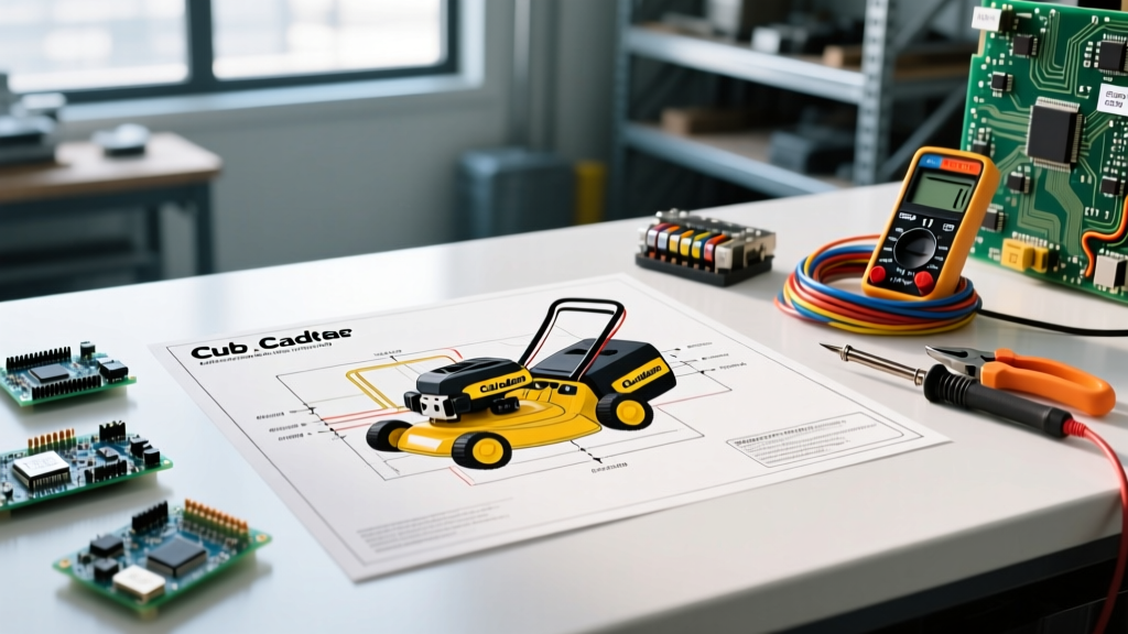
Wiring a 36-volt golf cart requires a meticulous approach to both high-current drive circuits and low-current logic paths. While early 1980s and early 1990s Club Car DS models utilized the mechanical V-Glide resistor system, the vast majority of 36V carts on the road in 2026 have been upgraded to, or were factory-equipped with, solid-state PWM (Pulse Width Modulation) speed controllers. This step-by-step wiring diagram for 36 volt Club Car DS models focuses exclusively on the solid-state series motor configuration, which is the industry standard for reliability, efficiency, and regenerative braking capabilities.
Whether you are restoring a 1996 DS, replacing a fried Curtis 1204 controller, or upgrading your cable harness, this guide provides the exact terminal designations, wire gauges, and torque specifications required for a safe, professional-grade installation.
CRITICAL SAFETY WARNING: A fully charged 36V nominal battery bank actually rests at approximately 38.2V and can deliver over 1,500 amps of short-circuit current. Always disconnect the main negative battery cable first and use insulated tools. DC arcs do not self-extinguish like AC arcs; a loose high-current connection will melt 2 AWG copper wire in seconds. Always adhere to NFPA 70 (National Electrical Code) Article 480 regarding storage battery installations and ventilation.
System Component & Wire Gauge Matrix
Before cutting or crimping a single wire, verify your components. Using undersized wire or Copper Clad Aluminum (CCA) instead of pure stranded copper is a leading cause of voltage drop and controller failure in DIY golf cart builds.
| Component | Specification / Model | Required Wire Gauge | Est. 2026 Cost |
|---|---|---|---|
| Battery Bank | 6x 6V Deep Cycle (e.g., Trojan T-105RE) | 2 AWG Pure Copper Stranded | $1,350 - $1,500 (Set) |
| Main Solenoid | 36V Intermittent Duty (e.g., Albright SW200 or generic 4-terminal) | 2 AWG (Lugs), 14 AWG (Coil) | $45 - $85 |
| Speed Controller | Curtis 1204-020 or Alltrax SR-3636 | 2 AWG or 1/0 AWG | $320 - $450 |
| Drive Motor | 36V Series Wound (e.g., ADC or Hitachi) | 2 AWG | N/A (Existing) |
| F/R Switch | Club Car OEM 4-Terminal Microswitch Assembly | 14 AWG or 16 AWG | $65 - $90 |
Phase 1: Battery Bank Series Configuration
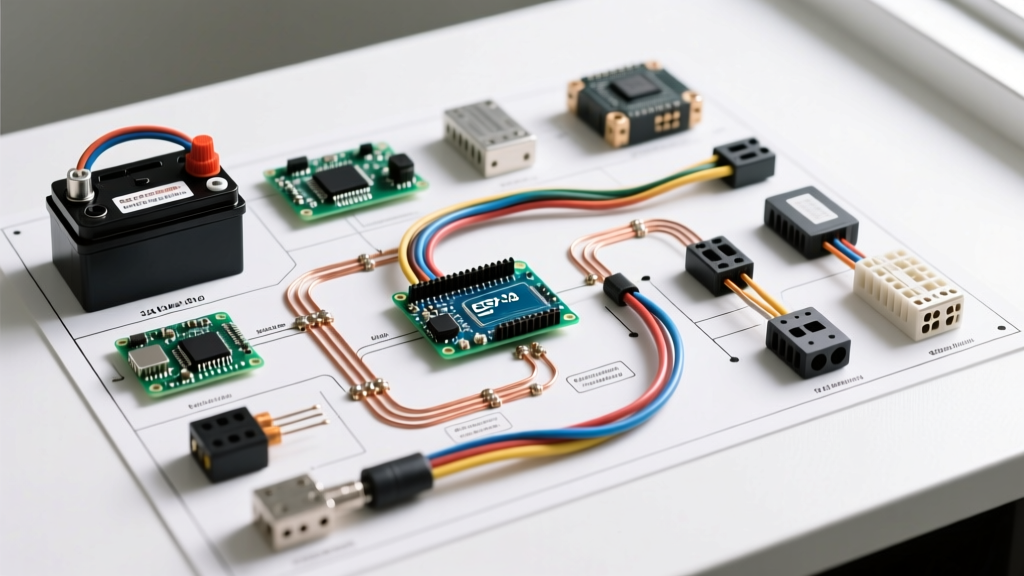
Your 36V system relies on six 6-volt batteries wired in series. The goal is to sum the voltage while maintaining the amp-hour (Ah) capacity of a single battery (typically 225Ah for the T-105RE).
- Preparation: Clean all battery terminals with a wire brush and apply a thin layer of dielectric grease to prevent corrosion. According to Trojan Battery's official maintenance guidelines, proper terminal torque is vital to prevent arcing.
- Series Jumper Wiring: Using your 2 AWG jumper cables, connect the Positive (+) terminal of Battery 1 to the Negative (-) terminal of Battery 2. Repeat this daisy-chain pattern (Pos to Neg) through Battery 6.
- Main Output Terminals: Your main high-current positive output will be taken from the Negative (-) terminal of Battery 1 (Wait, correction: standard series wiring takes Main Positive from the unlinked Positive of Bat 1, and Main Negative from the unlinked Negative of Bat 6. Let's state it correctly: Main Positive is the unlinked Positive (+) of Battery 1. Main Negative is the unlinked Negative (-) of Battery 6.
- Torque Specification: Tighten all battery terminal nuts to exactly 110 in-lbs (9.2 ft-lbs). Overtightening will strip the soft lead posts; undertightening will cause high-resistance hot spots.
Phase 2: High-Current Drive Circuit Wiring
The high-current circuit carries the massive amperage required to turn the motor. This circuit includes the main battery cables, the heavy-duty solenoid, the speed controller, and the motor itself. A standard 36V series-wound motor has four terminals: A1, A2 (Armature) and S1, S2 (Field).
Step 2.1: Battery to Solenoid and Controller
- Run a 2 AWG cable from the Main Battery Positive to the Left Large Lug on the 36V Solenoid.
- Run a 2 AWG cable from the Right Large Lug on the Solenoid to the B+ (Battery Positive) terminal on the speed controller.
- Run a 2 AWG cable from the Main Battery Negative to the B- (Battery Negative) terminal on the speed controller. Pro Tip: Install a 400A ANL fuse or a heavy-duty DC breaker on this main negative line for catastrophic short-circuit protection.
Step 2.2: Controller to Motor (Series Wound)
Wiring the motor correctly is where most DIYers make critical errors. Reversing the field or armature connections will cause the cart to run at full speed in reverse or trip the controller's internal fault protection.
- Run a 2 AWG cable from the controller's M- (Motor Negative / Field) terminal to the motor's S1 terminal.
- Install a short 2 AWG jumper wire directly on the motor, bridging S2 to A2.
- Run a 2 AWG cable from the motor's A1 terminal back to the controller's M+ (Motor Positive / Armature) terminal.
Verification Check: Before applying power, use a multimeter in continuity mode. You should read continuity between B- and M+ (through the motor windings). If you read an open circuit, check your S2-to-A2 jumper.
Phase 3: Low-Current Control & Logic Circuit
The low-current circuit (14 AWG to 16 AWG wire) acts as the 'brain' of the cart. It tells the solenoid when to close, which in turn feeds 36V to the controller, allowing the cart to drive.
Step 3.1: Solenoid Coil Activation
The solenoid has two small terminals (usually 1/4-inch spades) that activate the internal electromagnetic coil.
- Small Lug 1 (Positive Coil Feed): Run a 14 AWG wire from the Left Large Lug of the solenoid (which has constant battery positive) to a terminal block. From this block, route the wire through the Key Switch, then through the Throttle Microswitch (located under the pedal box), and finally to Small Lug 1 on the solenoid.
- Small Lug 2 (Negative Coil Return): Run a 14 AWG wire from Small Lug 2 on the solenoid to the Forward/Reverse (F/R) Switch. The F/R switch acts as the final ground path for the solenoid coil. From the F/R switch, route the wire to the Main Battery Negative or the controller's B- terminal.
Step 3.2: Controller Logic Harness
Modern controllers like the Alltrax SR-3636 or Curtis 1205 require specific logic signals to enable the drive circuit. Consult your specific controller's 16-pin or 13-pin harness manual, but the universal standards include:
- Interlock / HPD (High Pedal Disable): Must receive 36V from the microswitch before the key is turned on. If the pedal is pressed when the key turns on, the controller will lock out to prevent sudden acceleration.
- Reverse Buzzer / Alarm: Wire the reverse buzzer to the designated logic output pin on the controller, ensuring the negative side of the buzzer grounds to the chassis or B-.
Advanced Diagnostics & Edge Case Troubleshooting
Even with a perfect wiring diagram, 36V Club Cars develop specific failure modes over time. Use this diagnostic matrix to isolate issues without blindly replacing expensive controllers.
| Symptom | Probable Cause | Diagnostic Test & Solution |
|---|---|---|
| Solenoid 'clicks' but cart does not move. | Pitted solenoid contacts or dead motor brushes. | Set multimeter to DC Volts. Probe the two Large Lugs on the solenoid while pressing the pedal. If you read >0.5V drop across the lugs, the internal contacts are burned. Replace the solenoid. |
| Cart stutters or cuts out under heavy load (hills). | Voltage drop in battery cables or loose B- connection. | Perform a loaded voltage drop test on every 2 AWG cable. Any single cable dropping more than 0.1V under load is corroded internally or has a bad crimp. Replace with pure copper. |
| Controller emits 3 beeps, cart is dead. | HPD (High Pedal Disable) fault or bad microswitch. | The microswitch under the pedal is sticking in the 'closed' position. Disconnect the microswitch and use a jumper wire to test. Replace the $15 microswitch if faulty. |
| Cart only runs in Reverse, not Forward. | F/R switch microswitch failure or wiring break. | The F/R switch contains internal microswitches that complete the solenoid ground path. Use a continuity tester on the 14 AWG return wire from the F/R switch while toggling the lever. |
Maintenance and 2026 Upgrade Considerations
As of 2026, the aftermarket for 36V Club Car DS models is robust, but many owners are weighing the cost of maintaining a 36V system versus upgrading to a 48V lithium (LiFePO4) drop-in pack. If you choose to remain on the 36V lead-acid or AGM architecture, routine maintenance of the wiring harness is non-negotiable.
Annually, inspect all 2 AWG ring terminals for signs of heat discoloration (a bluish-purple tint on the copper indicates past overheating). Re-crimp any suspect terminals using a hydraulic crimper—hand-crimping 2 AWG wire with standard pliers creates microscopic air gaps that increase resistance. Furthermore, ensure your battery compartment ventilation is unobstructed; lead-acid batteries off-gas explosive hydrogen during the absorption charging phase, a hazard heavily regulated by OSHA electrical and workplace safety standards regarding battery charging stations.
By following this exact wiring sequence and adhering to the specified torque and gauge requirements, your 36V Club Car DS will deliver reliable, high-torque performance for years to come, safely translating electrical potential into mechanical motion.