
Pre-Installation Assessment: Choosing Your Delco Alternator
The Chevy 350 Small Block V8 is arguably the most popular engine platform in automotive history. Whether you are restoring a 1972 C10, swapping a carbureted 350 into a classic muscle car, or upgrading the charging system on a marine application, understanding the correct wiring diagram for Chevy 350 alternator configurations is critical. A flawed installation can lead to undercharging at idle, fried ECUs, or catastrophic electrical fires.
Before cutting a single wire, you must identify which alternator family your 350 is utilizing. General Motors (via Delco Remy) produced several internally and externally regulated alternators that bolt to the standard Chevy 350 passenger-side or driver-side brackets. As of 2026, the aftermarket and remanufactured pricing for these units has stabilized, but selecting the right amp rating for your specific electrical load is paramount.
Alternator Model Comparison & 2026 Pricing
| Alternator Model | Type | Typical Amp Output | Avg. 2026 Price (USD) | Best Application |
|---|---|---|---|---|
| Delco 10-SI | Internal Reg / 3-Wire | 63A - 94A | $75 - $95 | Stock carbureted 350s, minimal accessories |
| Delco 12-SI | Internal Reg / 3-Wire | 94A - 108A | $90 - $120 | Mild street builds, basic electric fans |
| Delco CS144 | Internal Reg / 4-Wire | 140A | $130 - $160 | High-load street rods, multiple fuel pumps |
| Powermaster 17294 | 1-Wire / High Output | 140A - 200A | $210 - $260 | Pro-touring, massive audio, EFI systems |
Note: Externally regulated alternators (like the early 10-DN) require a separate voltage regulator mounted on the radiator support. This guide focuses on the vastly more common internally regulated SI and CS series, which simplified the wiring diagram for Chevy 350 alternator swaps starting in 1973.
The Core Wiring Diagram: 3-Wire vs. 1-Wire Setups
When planning your harness, you must decide between a traditional 3-wire setup and a simplified 1-wire conversion. While 1-wire alternators are heavily marketed for their 'plug-and-play' simplicity, they introduce specific operational quirks that every builder must understand.
Expert Warning: A 1-wire alternator requires the engine to be revved to approximately 1,500 - 2,000 RPM upon initial startup to 'excite' the rotor and begin charging. If your Chevy 350 has a radical camshaft with a rough idle and you are running a 1-wire setup, the alternator may drop out of the charging circuit at stoplights, forcing the vehicle to run entirely on battery power.
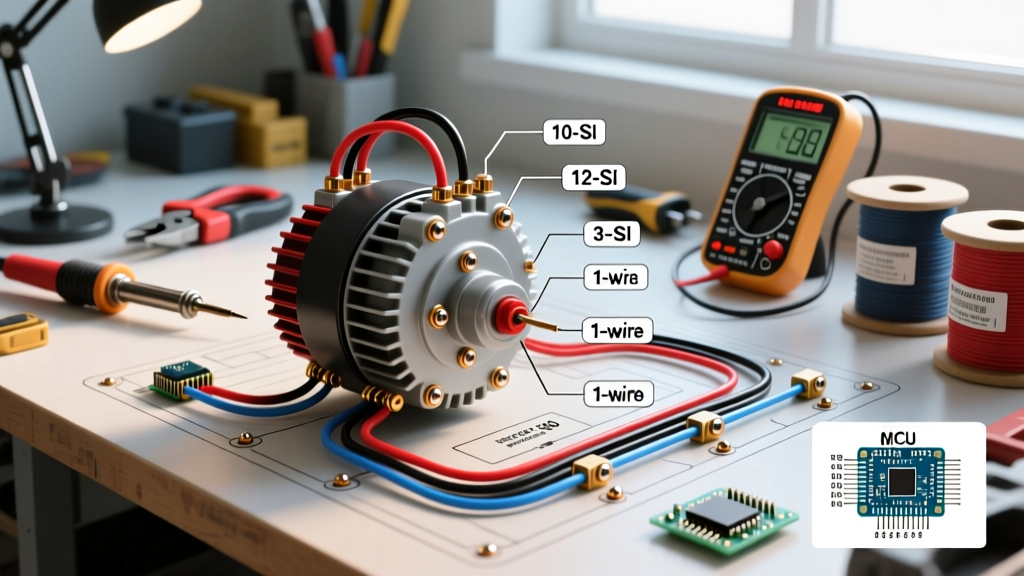
Terminal Identification (10-SI and 12-SI)
Looking at the rear of the alternator with the connector facing you, the terminals are arranged in a specific sequence:
- BAT (Battery) Terminal: The large threaded post. This is the main power output.
- Terminal 1 (Voltage Sense): The left pin in the 2-pin connector. This tells the internal regulator what the battery voltage actually is.
- Terminal 2 (Ignition / Field Excite): The right pin in the 2-pin connector. This provides the initial 12V 'kick' to turn the alternator on when the key is in the 'Run' position.
The 3-Wire Diagram Execution
For optimal voltage regulation, especially on a Chevy 350 with long wiring runs to the trunk-mounted battery or high-amp accessories, the 3-wire diagram is the gold standard.
- Main Charge Wire: Run from the BAT terminal directly to the positive battery terminal or the main starter junction block. Always install a 100A to 150A Mega Fuse within 8 inches of the battery positive.
- Sense Wire (Terminal 1): Run a dedicated wire from Terminal 1 directly to the battery positive post or the main distribution block. This ensures the regulator compensates for voltage drop across the main charge wire.
- Excite Wire (Terminal 2): Run from Terminal 2 to a 12V ignition-switched source. Critical Detail: If you are using an LED dash indicator light instead of an incandescent 194 bulb, you must wire a 56-ohm, 2-watt resistor in parallel. LEDs do not draw enough current to provide the initial field excitation, which will result in a no-charge condition at idle.
Wire Gauge Selection & Routing Specifications
Automotive environments subject wiring to extreme heat, vibration, and chemical exposure. Sizing your wire correctly prevents voltage drop and melting. According to the SAE J1128 standard for low-tension primary cable, automotive wire must withstand higher temperatures than standard household wire. Always use cross-linked polyethylene (XLPE) or TXL/GXL stranded copper wire.
AWG Sizing Matrix for Chevy 350 Alternators
| Circuit Function | Alternator Output | Recommended Wire Gauge (AWG) | Max Run Length (One Way) |
|---|---|---|---|
| Main Charge (BAT) | Up to 80A (10-SI) | 6 AWG | 6 Feet |
| Main Charge (BAT) | 80A - 120A (12-SI) | 4 AWG | 8 Feet |
| Main Charge (BAT) | 140A+ (CS144/PM) | 2 AWG or 1/0 AWG | 10 Feet |
| Sense (Term 1) | All Models | 12 AWG or 10 AWG | N/A (Low Current) |
| Excite (Term 2) | All Models | 14 AWG or 12 AWG | N/A (Low Current) |
Reference: While automotive standards dictate specific insulation types, baseline ampacity and voltage drop calculations can be cross-referenced with the NFPA 70 National Electrical Code guidelines for copper conductors, adjusted for the 12V-14V DC automotive environment.
Step-by-Step Installation & Routing Plan
The physical routing of the harness on a Chevy 350 is just as critical as the schematic. The classic Small Block generates immense radiant heat from the exhaust manifolds, which are typically located inches away from the alternator on the passenger side.
- Bracket Grounding Prep: Factory alternator brackets are often painted or powder-coated. Use a wire wheel or sandpaper to remove all coating from the mounting ears of the alternator and the mating surfaces on the cylinder head bracket. Poor grounding causes alternator whine and erratic voltage.
- Heat Shielding: Route the main 4 AWG charge wire down the passenger side inner fender, completely avoiding the exhaust manifold. Wrap the wire in split loom tubing, then secure it with Tesa 51036 PET cloth tape. Never use plastic zip-ties directly on the alternator case; the vibration will snap them. Use stainless steel Adel clamps (cushion clamps) instead.
- Sense Wire Fusing: Install a 5A inline ATC fuse on the Terminal 1 sense wire, located as close to the battery junction as possible. If the sense wire chafes against the intake manifold and shorts to ground, this fuse prevents the wire from acting as a glow plug and starting an engine bay fire.
- Engine-to-Chassis Ground: High-output alternators (140A+) will overwhelm the factory engine ground straps. Install a dedicated 1/0 AWG ground strap from the alternator mounting bracket directly to the vehicle chassis or firewall to ensure the internal regulator has a zero-resistance reference ground.
Troubleshooting Common Failure Modes
Even with a perfect wiring diagram for Chevy 350 alternator setups, real-world variables can introduce faults. Use a digital multimeter to diagnose these common issues. For comprehensive testing procedures, refer to the Fluke automotive testing guide regarding alternator ripple and voltage drop.
1. Overcharging (15.5V+ at the Battery)
Cause: The sense wire (Terminal 1) is broken, disconnected, or reading voltage from a bad ground. When the regulator cannot 'see' the battery, it defaults to maximum output to force a charge, boiling the battery acid and frying sensitive EFI computers (like a Holley Sniper or FiTech).
Fix: Perform a voltage drop test on the sense wire. With the engine running, measure the voltage between the battery positive post and Terminal 1. It should read less than 0.1V.
2. Alternator Whine Through the Audio System
Cause: Ground loops. The alternator case is grounded through a painted bracket, forcing the return current to seek alternative paths through the RCA shield grounds of your amplifier.
Fix: Verify the alternator case-to-engine block resistance (should be 0.00 ohms). Upgrade the main engine-to-chassis ground strap and ensure your audio amplifier is grounded to a bare metal point on the chassis, not a seatbelt bolt.
3. Diode Trio Burnout
Cause: Disconnecting the battery while the engine is running (a common but dangerous 'old-school' test). This creates a massive voltage spike (load dump) that instantly vaporizes the internal diode trio.
Fix: Never disconnect the battery on a running engine. If the diode trio is blown, the alternator will output AC ripple into the DC system. Test for AC voltage at the battery with the engine running; anything over 50mV AC indicates failed diodes requiring a rebuild or replacement.
Final Planning Checklist
- [ ] Verify alternator model (10-SI, 12-SI, CS144) and bracket alignment.
- [ ] Purchase TXL/GXL stranded wire in correct AWG sizes.
- [ ] Procure 56-ohm resistor if utilizing LED dash warning lights.
- [ ] Install Mega Fuse on main charge wire and 5A ATC on sense wire.
- [ ] Sand alternator and bracket mating surfaces for bare metal ground contact.
By meticulously following this installation planning guide and respecting the specific wiring diagram for Chevy 350 alternator configurations, you ensure a robust, fire-safe, and reliable charging system capable of handling modern electrical demands on a classic V8 platform.