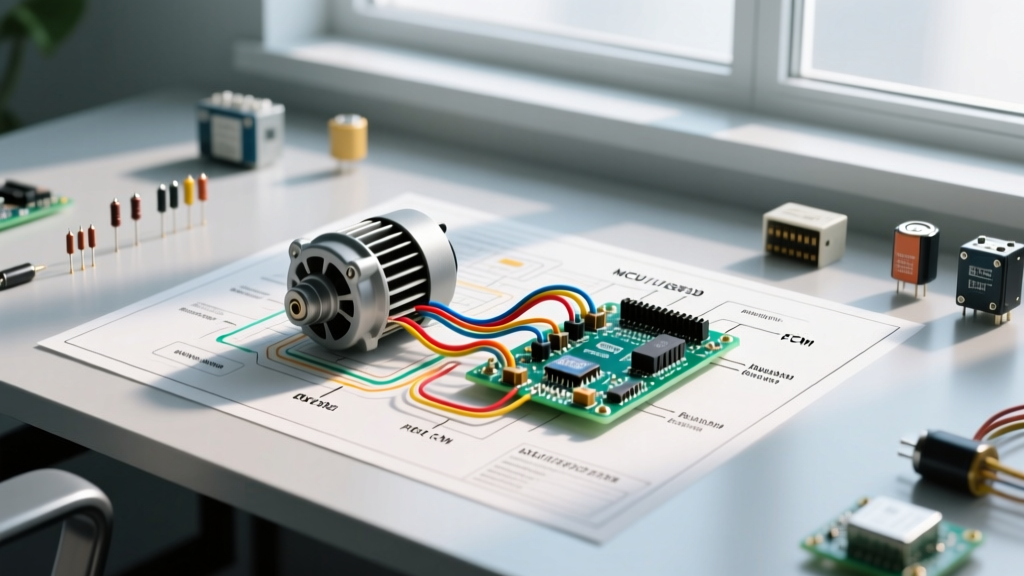

Introduction to Air Handler Motor Wiring
Understanding the wiring diagram for air handler systems is a fundamental skill for any HVAC technician or advanced DIYer. The air handler is the internal component of your split-system heat pump or central air conditioner, responsible for pushing conditioned air through your ductwork. At the heart of this unit is the blower motor, which requires precise electrical connections to operate efficiently and safely. Misinterpreting a schematic can lead to blown control boards, tripped breakers, or destroyed motor windings. In this comprehensive motor wiring tutorial, we will break down the exact schematics, terminal designations, and real-world wiring practices for both legacy and modern air handler units. Whether you are replacing a burned-out Permanent Split Capacitor (PSC) motor or upgrading to an Electronically Commutated Motor (ECM), mastering these diagrams is non-negotiable. According to the NFPA 70 (National Electrical Code), all HVAC branch circuits must be properly sized and grounded, making accurate diagram interpretation a matter of both performance and legal compliance.
PSC vs. ECM: Identifying Your Blower Motor Type
Before tracing a single wire on your schematic, you must identify the type of blower motor installed in your air handler. The wiring diagram for air handler units will look drastically different depending on whether the system uses a PSC or an ECM motor. The Department of Energy's updated fan efficiency standards have heavily pushed the industry toward ECM technology, meaning you will encounter both types in the field today.
Permanent Split Capacitor (PSC) Motors
PSC motors are the legacy workhorses of the HVAC industry. They are relatively simple, relying on a run capacitor to create a phase shift that keeps the motor spinning. A standard PSC motor (such as the Fasco A136 series) typically features three to five speed taps (Black for High, Blue for Med-High, Red for Med-Low, White for Low, and Brown/Brown-White for the capacitor). Wiring these requires connecting the line voltage, the common neutral, and the capacitor circuit.
Electronically Commutated Motors (ECM)
ECM motors (like the widely used Genteq 5195 or 3.0 series) are brushless DC motors with built-in microprocessors. They do not use external run capacitors. Instead, they rely on a 16-pin Molex connector that receives high-voltage power (120V/240V) and low-voltage control signals (24V AC) from the air handler control board. The wiring diagram for air handler ECM systems focuses heavily on the control board dip-switch configurations and the specific pinouts of the Molex harness rather than individual speed taps.
| Feature | PSC Blower Motor | ECM Blower Motor |
|---|---|---|
| Speed Control | Fixed taps (3-5 speeds) | Infinite variable speed via microprocessor |
| Capacitor Required? | Yes (Typically 5 MFD to 15 MFD) | No (Internal electronics handle phase shifting) |
| Average Replacement Cost | $120 - $180 (Motor only) | $650 - $950 (Motor + Control Module) |
| Wiring Complexity | Moderate (Speed taps + Capacitor) | High (16-pin harness + 24V logic signals) |
| Efficiency (Watts/CFM) | Low to Moderate | High (Meets latest DOE mandates) |
Decoding the Wiring Diagram for Air Handler Control Boards
The control board is the brain of the air handler. The wiring diagram for air handler systems will always feature a central block representing the Integrated Furnace Control (IFC) or Air Handler Control Board. Let us break down the two primary voltage sections you will see on the schematic.
High-Voltage (120V/240V) Motor Connections
For PSC motors, the high-voltage section of the diagram will show the L1 (Line) and L2 (Neutral/Common) connections. In a standard 120V residential air handler, L1 receives 120V AC from the main disconnect or breaker panel via a 15-amp or 20-amp circuit. The diagram will show L1 routing through a door interlock switch and a fuse before reaching the control board's 'L' or 'LINE' terminal. The neutral wire connects directly to the 'N' or 'NEUT' terminal on the board and splices directly to the motor's common winding. Crucial Note: Never wire a 120V air handler motor to a 240V supply. Doing so will instantly vaporize the control board's transformer and fry the motor windings. Always verify the supply voltage with a digital multimeter before making connections.
Low-Voltage (24V) Thermostat and Control Terminals
The low-voltage section of the wiring diagram for air handler units dictates how the thermostat communicates with the blower. The control board's transformer steps down 120V to 24V AC. You will see terminals labeled R (24V Hot), C (24V Common), G (Indoor Fan), Y (Cooling Contactor), W (Heating), and E (Emergency Heat). When the thermostat calls for cooling, it bridges the R and Y terminals, and simultaneously bridges R and G. The control board detects the 24V signal on the G terminal and energizes the internal blower relay, sending 120V to the PSC motor's high-speed tap or sending the logic signal to the ECM's Molex harness.
Safety Warning: Always lock out and tag out (LOTO) the main electrical disconnect before opening the air handler blower compartment. According to OSHA electrical safety guidelines, working on live HVAC circuits exposes technicians to severe arc flash and electrocution hazards. Verify zero voltage at the control board's LINE and NEUT terminals using a CAT III rated multimeter before touching any wires.
Step-by-Step Motor Wiring Tutorial: PSC Blower Replacement
Replacing a PSC motor is the most common task requiring interpretation of the wiring diagram for air handler units. Follow these precise steps to ensure a safe and functional installation.
- Disconnect Power and Verify: Turn off the dedicated HVAC breaker at the main panel and pull the outdoor disconnect. Use a non-contact voltage tester and a multimeter to confirm zero voltage at the air handler control board.
- Document the Existing Wiring: Before removing a single wire, take high-resolution photos of the control board, the capacitor terminals, and the motor junction box. Manufacturers often use non-standard color codes; your photo is your ultimate reference.
- Disconnect the Run Capacitor: Locate the dual run capacitor (usually a silver or black oval cylinder). Identify the 'FAN' or 'F' terminal. Using a 1/4-inch nut driver or spade puller, remove the brown wire from the FAN terminal. Never use pliers to yank the spade connector, as this will stretch the female terminal and cause a high-resistance connection that will melt the wiring harness.
- Wire the New Motor Speed Taps: Consult the new motor's schematic. Connect the Black (High Speed) wire to the 'COOL' or 'H' terminal on the control board. Connect the White (Common) wire to the neutral splice. Cap off any unused speed taps (like Red or Blue) individually with wire nuts and electrical tape. Never twist unused speed taps together; this will create a short circuit through the motor's auxiliary windings and destroy the motor upon startup.
- Connect the Capacitor Circuit: Connect the motor's Brown wire to the 'FAN' terminal on the dual run capacitor. Connect the Brown with White Stripe wire to the 'C' (Common) terminal on the capacitor. If your new motor requires a separate start capacitor and relay, follow the manufacturer's specific schematic for the potential relay wiring.
- Terminate with Proper Crimps: Use a professional ratcheting crimping tool (such as the Titan 1147) to attach 1/4-inch fully insulated female spade connectors to the motor leads. Do not rely on twist-on wire connectors for high-vibration motor connections.
Common Failure Modes and Troubleshooting Edge Cases
Even when you follow the wiring diagram for air handler systems perfectly, edge cases and component failures can occur. Understanding these specific failure modes will save you hours of diagnostic time.
- The 'Y' and 'C' Terminal Short: A very common mistake during thermostat wiring is allowing the bare copper strands of the 'Y' (Cooling) wire to touch the 'C' (Common) wire. Because the control board's transformer is not always internally fused on the secondary side, this dead short will instantly blow the 3-amp or 5-amp automotive-style blade fuse on the control board. If your air handler has no power and the thermostat screen is dead, check this 3A ATC fuse first.
- ECM Molex Connector Pin Damage: When troubleshooting an ECM motor, technicians often attempt to back-probe the 16-pin Molex connector while the system is powered. The pins are incredibly fragile. Bending a pin or shorting the 24V logic pin to the 120V line pin will permanently destroy the $800 ECM control module. Always de-energize the system before unplugging or inspecting the Molex harness.
- Capacitor Terminal Miswiring (HERM vs. FAN): On a dual run capacitor, the 'HERM' terminal powers the outdoor compressor's start winding, while the 'FAN' terminal powers the indoor air handler blower. If you accidentally wire the air handler's brown capacitor wire to the 'HERM' terminal, the blower motor will attempt to start with the wrong phase angle. It will either run backward, hum loudly and trip its internal thermal overload, or cause the compressor to fail to start due to a voltage drop across the shared common winding.
- Undersized Control Wiring: The EPA Energy Star HVAC guidelines emphasize proper system commissioning for efficiency. Using 20 AWG or 22 AWG wire for long thermostat runs (over 50 feet) causes excessive voltage drop. The control board may see 21V instead of 24V, causing the blower relay to chatter or fail to pull in. Always use 18 AWG solid copper wire for 24V control circuits to ensure adequate amperage delivery to the relays and contactors.
Final Thoughts on Air Handler Schematics
Mastering the wiring diagram for air handler units requires a methodical approach. Always identify your motor type, respect the boundary between high-voltage line power and low-voltage control logic, and use proper termination techniques. By understanding the underlying electrical principles—rather than just blindly following colored wires—you will be equipped to diagnose and repair any blower motor circuit you encounter in the field.