
Strategic Installation Planning: Beyond the Power Cord
Installing a modern Frigidaire refrigerator requires more than simply sliding the unit into an alcove and plugging it into the nearest outlet. For 2026 kitchen remodels and appliance upgrades, understanding the wiring diagram for Frigidaire refrigerator systems is a critical step in pre-installation planning. Whether you are installing a standard top-freezer model like the FFTR1835VS or a high-capacity Frigidaire Gallery French Door unit (GRFS2853AF), the internal electrical architecture dictates your external circuit requirements. Failing to align your home electrical panel with the appliance schematic can lead to nuisance tripping, compressor failure, or voided warranties.
This installation planning guide bridges the gap between the manufacturer schematic and the National Electrical Code (NEC), providing electricians, contractors, and advanced DIYers with the exact specifications needed for a flawless setup.
Electrical Prerequisites and Circuit Sizing Matrix
According to the National Fire Protection Association (NFPA) and NEC Article 210.23, major kitchen appliances require dedicated branch circuits. While older homes often daisy-chain refrigerators onto general kitchen lighting circuits, modern Frigidaire models with dual-evaporator systems and adaptive defrost boards draw significant transient current during compressor startup.
Below is the 2026 electrical requirement matrix for popular Frigidaire series. Use this to verify your breaker panel capacity and wire gauge before running new Romex.
| Frigidaire Model Series | Type / Capacity | Voltage / Hz | Rated Amperage | Min. Circuit Ampacity | Required Breaker & Wire |
|---|---|---|---|---|---|
| FFTR1835VS | Top Freezer / 18.3 cu. ft. | 120V / 60Hz | 1.5A - 2.5A | 15A | 15A Breaker / 14 AWG |
| GRFS2853AF (Gallery) | French Door / 27.8 cu. ft. | 120V / 60Hz | 4.0A - 6.5A | 15A (20A Rec.) | 20A Breaker / 12 AWG |
| PRMC2285AF (Professional) | Counter-Depth / 22.6 cu. ft. | 120V / 60Hz | 5.0A - 8.0A | 20A | 20A Breaker / 12 AWG |
Cost Note: As of early 2026, hiring a licensed electrician to pull a new dedicated 20-amp circuit with 12/2 NM-B wire and a standard duplex receptacle averages between $280 and $450, depending on drywall repair and panel accessibility.
Decoding the Wiring Diagram for Frigidaire Refrigerator Components
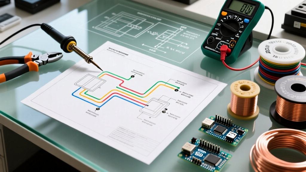
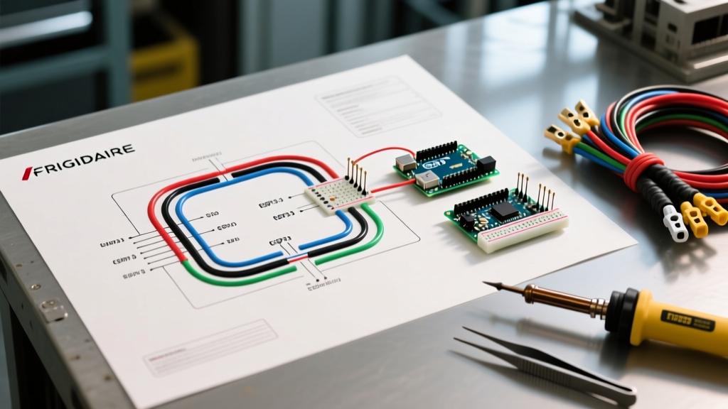
The schematic located inside the lower kickplate grille or the rear machine compartment is your roadmap. Frigidaire utilizes standard electrical symbols, but understanding how the main electronic control board (ECB) interacts with the load components is vital for planning your diagnostic approach post-installation.
The L1 and Neutral Rails
Every Frigidaire schematic is divided into two primary power rails: L1 (Line 1 - Hot, typically Black) and N (Neutral, typically White). The 120V AC supply enters the main harness and feeds the ECB. The ECB then acts as a series of solid-state relays, switching the L1 voltage to specific components (like the ice maker heater or evaporator fan) while the Neutral remains a continuous return path. When planning your installation, ensure the receptacle's hot/neutral polarity is strictly verified using a $15 circuit analyzer; reversed polarity will prevent the ECB's internal safety relays from energizing the compressor.
Compressor and PTC Start Relay Circuit
The compressor is the highest inductive load on the diagram. Modern Frigidaire units use a PTC (Positive Temperature Coefficient) start relay paired with an overload protector. The schematic will show three compressor terminals: C (Common), R (Run), and S (Start).
- Common (C): Receives L1 voltage through the overload protector and the ECB's compressor relay.
- Run (R): Connected directly to the Neutral rail.
- Start (S): Connected to the Neutral rail via the PTC relay and start capacitor (if equipped).
Installation Edge Case: If your installation site experiences frequent voltage sags (common in rural areas or at the end of long wire runs), the PTC relay may fail to disengage, causing the compressor to overheat and trip the thermal overload. If your multimeter reads below 110V at the receptacle under load, consult the schematic to verify if your model supports a hard-start capacitor kit to mitigate LRA (Locked Rotor Amperage) spikes.
Defrost System and Dual-Evaporator Wiring
High-end Gallery and Professional models feature dual-evaporator systems, meaning the wiring diagram will show separate circuits for the fresh-food evaporator fan and the freezer evaporator fan. The defrost heater (typically a 120V, 300W-500W glass-tube or Calrod element) is wired in series with a bi-metal defrost thermostat.
According to the Frigidaire Official Support Portal, the ECB initiates the defrost cycle based on compressor run-time algorithms rather than a simple mechanical timer. The schematic will highlight the 'Defrost Heater' and 'Defrost Sensor' lines. During installation planning, ensure that the dedicated circuit can handle the simultaneous draw of the compressor (approx. 4A) and the defrost heater (approx. 3.5A) if the unit initiates a forced defrost during initial diagnostic mode.
The GFCI Nuisance Tripping Dilemma (NEC Compliance)
One of the most hotly debated topics in 2026 appliance installation is the requirement for GFCI (Ground Fault Circuit Interrupter) protection in kitchens. The NEC mandates GFCI protection for all receptacles serving kitchen countertops. However, placing a refrigerator on a GFCI-protected circuit is a known cause of nuisance tripping due to the transient inductive spikes generated by the compressor motor and the defrost heater's moisture exposure.
Critical Code Interpretation: The NEC generally allows an exception for a dedicated receptacle serving a single appliance (like a refrigerator) that does not serve the countertop surface. Always install a standard, non-GFCI 15A or 20A duplex receptacle behind the fridge on its own dedicated breaker to prevent spoiled food from phantom GFCI trips. Verify this with your local AHJ (Authority Having Jurisdiction), as local municipal codes in cities like Chicago or New York may have stricter amendments.
Step-by-Step Pre-Installation Electrical Checklist
Before the delivery truck arrives, complete this electrical verification checklist based on the unit's schematic requirements:
- Verify Circuit Dedication: Turn off the breaker designated for the fridge. Verify that no other outlets, lights, or appliances lose power. The Consumer Product Safety Commission (CPSC) strongly recommends dedicated circuits for major cooling appliances to prevent fire hazards from overloaded wires.
- Check Receptacle Polarity and Ground: Use a digital receptacle tester. The schematic requires a true equipment grounding conductor (EGC) to safely route fault currents from the compressor chassis back to the panel.
- Measure Voltage Under Load: Plug in a high-draw tool (like a hair dryer) into the fridge receptacle and measure the voltage. It must not drop below 108V (120V - 10%).
- Inspect the Power Cord: Frigidaire refrigerators typically ship without a power cord. Purchase a 3-prong, 120V, 15-amp or 20-amp UL-listed appliance cord. Do not use a 4-prong range cord with an adapter.
- Clear the Strain Relief: Ensure the rear machine compartment's strain relief bracket is intact to prevent the power cord from vibrating against the compressor's copper discharge line, which can melt the insulation and cause a dead short to ground.
Troubleshooting Wiring Faults Using the Schematic
If the unit fails to cool post-installation, use the wiring diagram to isolate the fault. Set your multimeter to the Ohms (Ω) setting and disconnect power.
- Testing the Defrost Heater: Locate the heater wires on the schematic. Disconnect the harness and measure across the heater terminals. A reading between 20Ω and 50Ω indicates a healthy element. An 'OL' (Open Line) reading means the glass tube is fractured and requires replacement.
- Testing the Evaporator Fan Motor: The diagram will show the ECM (Electronically Commutated Motor) or standard shaded-pole motor. If the ECB is sending 120V to the fan terminals but the motor is silent, the motor winding is open. Note: ECM motors require a specific DC voltage signal from the board; do not apply 120V AC directly to an ECM motor during testing, or you will destroy it.
Final Installation Directives
Properly interpreting the wiring diagram for Frigidaire refrigerator models ensures that your installation is safe, code-compliant, and optimized for the appliance's lifespan. By matching your branch circuit to the specific amperage and transient load requirements outlined in the manufacturer's schematic, you eliminate the most common causes of early compressor failure and control board burnout. Always keep a digital or physical copy of the schematic taped inside the lower front grille for future service technicians.