
Decoding the Wiring Diagram for Car Amplifier and Subwoofer Systems
Integrating a high-output mono amplifier and subwoofer into a modern vehicle requires more than just following a generic schematic. As automotive electrical architectures have evolved—particularly with the proliferation of start-stop systems, hybrid powertrains, and fully electric vehicles (EVs) in 2026—the standard wiring diagram for car amplifier and subwoofer installations must be adapted to handle complex voltage regulation and CAN-bus monitoring. A flawed installation doesn't just result in poor bass response; it can trigger check-engine lights, drain auxiliary batteries, or cause catastrophic thermal failure.
This vehicle-specific guide breaks down the exact wiring topology, wire gauge mathematics, and modern edge-case solutions required for a flawless, high-current audio upgrade.
The Core Topology: 5 Essential Wire Paths
Every reliable wiring diagram for car amplifier and subwoofer setups revolves around five distinct circuits. Misrouting or undersizing any of these will bottleneck your system's performance.
- Main Power (B+): Runs directly from the vehicle's positive battery terminal to the amplifier's B+ input. Must be fused within 18 inches of the battery.
- Chassis Ground (B-): Connects the amplifier's ground terminal to bare, unpainted chassis metal. Must be kept under 18 inches in length.
- Remote Turn-On (REM): A low-current (1-2A) 12V signal that tells the amplifier's internal relay to engage. Sourced from the head unit's remote wire or a CAN-bus triggered relay.
- RCA Signal Cables: Low-voltage shielded coaxial cables carrying the pre-amplified audio signal. Must be routed on the opposite side of the vehicle from the main power wire to prevent electromagnetic interference (EMI).
- Speaker Wire: High-current output wiring from the amplifier to the subwoofer voice coils.
Wire Gauge Matrix and the OFC vs. CCA Debate
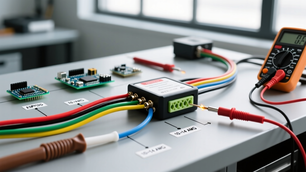
When consulting a wiring diagram for car amplifier and subwoofer applications, selecting the correct American Wire Gauge (AWG) is critical. According to The Engineering Toolbox, wire resistance increases exponentially with length. Furthermore, the market is flooded with Copper-Clad Aluminum (CCA) wire, which is fundamentally unsuited for high-draw subwoofer amplifiers.
| Amplifier Fuse Rating | Wire Length (0-15 ft) | Wire Length (15-25 ft) | Material Requirement |
|---|---|---|---|
| 30A - 50A | 8 AWG | 4 AWG | OFC or CCA acceptable |
| 50A - 80A | 4 AWG | 2 AWG | OFC Highly Recommended |
| 80A - 150A | 2 AWG | 1/0 AWG | OFC Mandatory |
| 150A - 250A+ | 1/0 AWG | 2/0 AWG | OFC Mandatory |
Why Oxygen-Free Copper (OFC) is Non-Negotiable for High Power
CCA wire contains an aluminum core with a thin copper plating. Aluminum has only 61% of the conductivity of copper. For a 1200W Class D amplifier drawing 100+ amps on bass transients, CCA wire will experience severe voltage drop, causing the amp's internal protection circuit to trigger (flashing protect mode). Furthermore, CCA oxidizes rapidly at crimp terminals, creating high-resistance hot spots that can melt insulation and start vehicle fires. Always verify your wire is certified OFC.
Step-by-Step Vehicle-Specific Installation Flow
Follow this sequence to execute the wiring diagram for car amplifier and subwoofer systems safely, adhering to Mobile Electronics Certified Professional (MECP) best practices.
Step 1: Power Wire Routing and Firewall Penetration
- Disconnect the Battery: Always remove the negative terminal first to prevent short circuits.
- Locate a Factory Firewall Grommet: Never drill a new hole in the firewall if a factory grommet is available. Modern vehicles use thick, sound-deadened steel that is difficult to pierce cleanly.
- Pierce, Don't Cut: Use a specialized grommet piercing tool or a blunt awl to create a small slit in the rubber. Feed the OFC power wire through. This maintains the factory waterproof and fume-proof seal, preventing carbon monoxide from entering the cabin.
- Install the Main Fuse: Crimp an ANL or MIDI fuse holder onto the power wire within 18 inches of the positive battery terminal. Do not use AGU fuses for draws over 60A, as their internal glass/sand construction cannot handle high transient currents without arcing.
Step 2: The 18-Inch Ground Rule
The ground connection is responsible for completing the circuit and dissipating heat. Locate a heavy-gauge structural bolt (e.g., a seatbelt anchor or strut tower bolt) within 18 inches of the amplifier.
- Remove the bolt and sand away all paint, primer, and rust using 80-grit sandpaper until bare, shiny metal is exposed.
- Crimp a heavy-duty copper ring terminal onto your ground wire.
- Secure the terminal to the bare metal and coat the area with dielectric grease or clear nail polish to prevent future oxidation.
Step 3: Signal Integration and Remote Turn-On
If your vehicle features a premium factory audio system (e.g., Bose, Harman Kardon, or Mark Levinson), the factory amplifier likely outputs a high-level, equalized signal. You must use a high-quality Line Output Converter (LOC) or a DSP with high-level inputs to flatten the signal before sending it via RCA cables to your subwoofer amplifier. For the remote turn-on wire, utilize a CAN-bus module or an audio-sense LOC to prevent the subwoofer from turning on when the vehicle is off, which would drain the battery.
2026 Edge Cases: Hybrids, EVs, and Start-Stop Systems
Modern vehicle electrical systems present unique challenges that older wiring diagrams fail to address.
Electric Vehicles (EVs) and DC-DC Converters
In vehicles like the Tesla Model Y, Ford F-150 Lightning, or Rivian R1T, there is no traditional alternator. The 12V accessory system is maintained by a DC-DC step-down converter from the high-voltage traction battery. These converters are typically rated for 150A to 200A total chassis load. If your vehicle's ECU, lighting, and HVAC are drawing 80A, and you install a 150A audio fuse, you risk tripping the DC-DC converter's overcurrent protection, shutting down the entire 12V system while driving. Solution: Install a secondary auxiliary AGM battery in the trunk with a smart battery isolator to handle audio transients independently.
Start-Stop Technology Voltage Sag
Internal combustion vehicles with auto start-stop technology will shut off the engine at red lights. When the engine restarts, the starter motor can pull 400+ amps, causing the 12V system voltage to sag to 9V or lower. This voltage drop will cause your subwoofer amplifier to shut off and restart, producing a loud, damaging 'pop'. To mitigate this, wire a 2.0 Farad digital stiffening capacitor or a dedicated auxiliary lithium-iron-phosphate (LiFePO4) audio battery near the amplifier.
Troubleshooting Real-World Failure Modes
Even with a perfect wiring diagram for car amplifier and subwoofer setups, tuning errors can mimic wiring faults. As noted by audio engineering experts at Audioholics, proper gain staging is paramount.
Alternator Whine (Ground Loops)
Symptom: A high-pitched whining noise that increases in pitch with engine RPM.
Cause: A ground loop occurs when the head unit and the amplifier are grounded at different electrical potentials, causing EMI to enter the RCA shields.
Fix: Ensure both the head unit (or DSP) and the amplifier share the exact same ground point, or use RCA cables with 100% braided shielding. Never run RCA cables parallel to the main power wire.
Amplifier Clipping and Thermal Shutdown
Symptom: Bass sounds distorted, and the amplifier becomes too hot to touch, eventually entering protect mode.
Cause: The gain knob is set too high, sending a square wave to the subwoofer. This generates massive amounts of DC heat rather than AC audio movement.
Fix: The gain knob is not a volume knob; it is a sensitivity matcher. Use a True RMS Digital Multimeter (like the Fluke 87V) to set your amplifier's output voltage. Calculate the target voltage using the formula: V = √(P × R). For a 500W amp at 2 ohms, the target AC voltage is √(500 × 2) = 31.62V. Play a 50Hz 0dBFS sine wave test tone, disconnect the subwoofer, and adjust the gain until the multimeter reads exactly 31.62V.
Expert Insight: Never rely on your ears to set the gain on a subwoofer amplifier. Human hearing is highly susceptible to fatigue and cabin resonance, which will inevitably lead to under-gaining (leaving power on the table) or over-gaining (destroying voice coils).
For comprehensive, vehicle-specific wiring schematics and harness pinouts, always consult your vehicle's service manual or trusted automotive electrical databases like Crutchfield's Installation Guides. By respecting the physics of high-current DC circuits and adapting to modern vehicle architectures, your car amplifier and subwoofer installation will deliver reference-quality bass for years to come.