
Applying Motor Control Logic to High-Amperage Resistive Loads
When approaching a 240 volt dual element 240v electric water heater wiring diagram, many residential installers treat it as basic plumbing-adjacent work. However, from a motor wiring and heavy-load control perspective, the dual-thermostat setup is essentially a manual-transfer, non-simultaneous interlock circuit. Just as we use interlocking contactors to prevent a 3-phase motor from simultaneously engaging forward and reverse, a dual-element water heater uses a priority-switching thermostat to prevent both 4500W resistive elements from energizing at the same time. If both elements engaged simultaneously, the current draw would spike to 37.5 amps, instantly tripping a standard 30A breaker and risking catastrophic thermal runaway.
In this tutorial, we will dissect the 240V dual-element schematic using the same rigorous analytical framework applied to industrial motor starters. We will cover exact terminal routing, National Electrical Code (NEC) load calculations, and the specific failure modes that mimic welded motor contactors.
Load Calculations and 2026 Component Sizing Matrix
Before pulling wire, we must establish the baseline electrical parameters. According to the NFPA 70 (National Electrical Code) Article 422.13, storage water heaters of 120 gallons or less must be sized at 125% of the nameplate load. For a standard 4500W element at 240V, the base amperage is 18.75A. Multiplying by 1.25 yields 23.43A, dictating a minimum 25A breaker. However, because 10 AWG copper wire is the standard minimum for this circuit and is rated for 30A, a 30A double-pole breaker is the universal standard.
| Parameter | Specification | Estimated 2026 Cost |
|---|---|---|
| Element Wattage (x2) | 4500W (Non-Simultaneous) | $15 - $25 per element |
| Operating Voltage | 240V AC (Single Phase) | N/A |
| Max Amperage Draw | 18.75A per element | N/A |
| Branch Circuit Breaker | 30A Double-Pole (240V) | $14 - $22 |
| Wire Gauge & Type | 10 AWG (10/2 NM-B or THHN) | $1.65 - $2.10 / ft |
| Element Resistance | 12.8 Ohms | N/A |
The Non-Simultaneous "Interlock" Diagram Explained
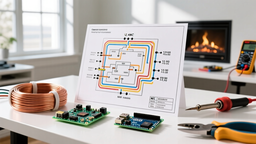
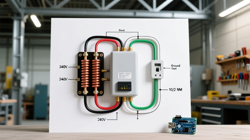
The core of the 240 volt dual element 240v electric water heater wiring diagram relies on a priority logic system. The upper thermostat acts as the primary controller, while the lower thermostat acts as a secondary fallback. This is functionally identical to a lead-lag motor control setup used in duplex pump stations.
Upper Thermostat Priority Routing (The "Contactor")
The upper thermostat contains a double-throw internal switch mechanism. When the water temperature in the top half of the tank drops below the set point (typically 120°F), the upper thermostat "closes" its primary contact. Line 1 (L1) voltage is routed directly to the upper heating element. Simultaneously, the internal interlock breaks the connection to the lower thermostat, ensuring the lower element receives zero voltage. This priority ensures that the hot water at the top of the tank—where the outlet dip tube draws from—is heated first, providing rapid recovery for the user.
Lower Thermostat Fallback Routing
Once the upper thermostat satisfies its temperature set point, the internal switch flips. It cuts power to the upper element and routes L1 voltage down to the lower thermostat's line terminal. The lower thermostat then evaluates the temperature at the bottom of the tank. If heat is needed, it closes its single-pole switch, sending L1 to the lower element. Because L2 is continuously fed to both elements, the completion of the circuit at the lower thermostat energizes the bottom 3000W-4500W load.
Step-by-Step Wiring Execution Guide
When executing the physical wiring, precision at the terminal blocks is critical. Loose connections on an 18.75A continuous load will generate massive resistive heat, melting the thermostat housing. Always torque terminals to manufacturer specifications (usually 12-15 in-lbs).
- Lockout/Tagout & Verification: Turn off the 30A double-pole breaker. Use a non-contact voltage tester (NCVT) and a CAT III multimeter to verify 0V across L1 and L2, and 0V from L1/L2 to ground. Treat this step with the same severity as verifying a 480V motor disconnect.
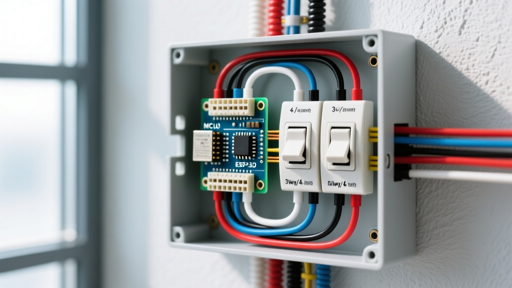
- Route the 10/2 NM-B Cable: Feed the 10/2 cable through the knockout at the top of the water heater junction box. Secure it with a 3/4-inch NM cable connector. Leave at least 6 inches of working length inside the box.
- Terminate Line Voltage (Upper Thermostat): Connect the Black wire (L1) to the top-left terminal of the upper thermostat (often labeled Line or L1). Connect the White wire (which must be wrapped in black electrical tape or painted black to re-identify it as a hot conductor per NEC 200.7) to the top-right terminal (L2).
- Wire the Upper Element & Interlock Drop: Run a jumper wire from the bottom-left terminal of the upper thermostat to the left screw of the upper heating element. Run a second jumper wire from the bottom-right terminal of the upper thermostat down to the top-left terminal of the lower thermostat.
- Route L2 to Lower Thermostat & Upper Element: The top-right terminal of the upper thermostat (L2) typically features a secondary screw or an internal jumper. Run a wire from this L2 source directly to the right screw of the upper heating element, and continue a daisy-chain drop down to the top-right terminal of the lower thermostat.
- Terminate the Lower Element: Run wires from the bottom-left and bottom-right terminals of the lower thermostat directly to the left and right screws of the lower heating element, respectively.
- Establish the Equipment Ground: Connect the bare copper ground wire from the 10/2 cable to the green grounding screw inside the junction box, and run a secondary 10 AWG bare copper jumper from the box to the green grounding screw on the water heater's outer metal jacket. Proper grounding is non-negotiable for fault-current clearing.
2026 NEC Code Alert: Under the latest adoptions of OSHA Electrical Safety Standards and NEC Article 250, the equipment grounding conductor (EGC) must be sized to clear the fault current of the 30A breaker. While 10 AWG copper is standard, if your circuit run exceeds 100 feet, you must upsize to 8 AWG wire to mitigate voltage drop, and consequently upsize your ground wire to 8 AWG as well.
Troubleshooting Edge Cases: "Welded Contacts" and Element Burnout
In motor control circuits, contactors can weld shut due to high inrush currents. While resistive water heater elements lack the inductive inrush of a motor, the thermostats are still mechanical bimetallic switches that can suffer from "welded contacts" or pitting over thousands of cycles. According to data from the U.S. Department of Energy, thermostat and element failures account for the vast majority of electric water heater service calls.
- Symptom: Tripped Breaker & Boiling Water. If the upper thermostat contacts weld shut, it will continuously feed L1 to the upper element even after the set point is reached. The water will boil, the pressure relief valve (TPR) will discharge, and the thermal cutoff (ECO) on the thermostat should trip. If the breaker trips before the ECO, you likely have a shorted element. Test: Disconnect wires and measure element resistance. A reading of 12.8 Ohms is healthy; a reading of 0 Ohms or continuity to the ground screw indicates a burnt-out, shorted element.
- Symptom: Lukewarm Water & Long Recovery. If the upper thermostat's internal interlock fails to route power to the lower thermostat after the top half is heated, the lower element will never engage. The tank will only utilize its top 25 gallons of hot water. Test: Use a multimeter to check for 240V at the lower thermostat's Line terminals while the upper tank is fully heated. If 0V is present, the upper thermostat interlock is defective and must be replaced.
- Symptom: Melted Wire Insulation at Terminals. This is strictly a mechanical failure caused by insufficient torque on the terminal screws. The resulting micro-arcing generates intense localized heat. Cut back the damaged 10 AWG wire, strip fresh insulation, and consider applying an anti-oxidant compound (like Noalox) if using aluminum wire, though copper is heavily preferred for 2026 installations.
Final Verification and Energization
Before replacing the insulation and junction box covers, perform a final visual audit of the 240 volt dual element 240v electric water heater wiring diagram layout. Ensure no bare copper strands are splaying outside the terminal blocks. Replace all access panels securely; most modern water heaters feature a physical safety interlock switch that prevents power from reaching the elements if the panel is removed. Re-energize the 30A breaker, clamp an ammeter around one of the hot conductors, and draw hot water from a nearby faucet. You should see a clean 18.75A draw as the upper element engages, confirming a safe, code-compliant, and logically sound installation.