
Even as the HVAC industry shifts heavily toward smart home integration in 2026, millions of residential systems still rely on the legendary White-Rodgers thermostat lineup. Now largely managed under the Emerson umbrella and rebranded for modern applications as Sensi, legacy White-Rodgers models like the 1F80-361 and 1F78-144 remain ubiquitous. When your heating or cooling system fails, guessing wire placements is a fast track to blowing your furnace control board fuse. Learning how to properly interpret a wiring diagram for a White Rodgers thermostat is the most systematic way to isolate 24VAC control circuit faults without throwing expensive parts at the problem.
The Anatomy of a White-Rodgers Sub-Base Wiring Diagram
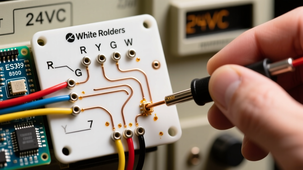
Unlike digital smart thermostats that rely on internal software routing, classic White-Rodgers units use a physical sub-base with a terminal block and, in some heat pump models, physical jumper pins. The wiring diagram printed on the inside of the sub-base cover or included in the installation manual maps the low-voltage Class 2 circuit directly to the HVAC contactors and relays.
| Terminal | Function | Typical Wire Color | Voltage State (Active) |
|---|---|---|---|
| R / RC / RH | 24VAC Power (Hot) | Red | 24-28 VAC constant |
| C | Common (Ground) | Blue / Black | 0 VAC (Reference) |
| W | Primary Heat | White | 24 VAC when calling for heat |
| Y | Compressor / Cool | Yellow | 24 VAC when calling for cool |
| G | Indoor Blower Fan | Green | 24 VAC when fan is on |
| O / B | Heat Pump Reversing Valve | Orange / Dark Blue | 24 VAC (O=Cool, B=Heat) |
According to the National Electrical Code (NEC) Article 725, these thermostat circuits are classified as Class 2 remote-control and signaling circuits. This means they are isolated from line voltage, but a short circuit can still destroy the low-voltage transformer or the 3-amp automotive blade fuse located on your furnace’s Integrated Furnace Control (IFC) board.
Troubleshooting Scenario 1: Blank Display and Dead HVAC System
If your White-Rodgers 1F80 programmable thermostat has a blank screen and the HVAC system is completely unresponsive, your first instinct might be to replace the batteries. However, if your unit is hardwired using the C (Common) and R (Power) terminals, a blank screen indicates a loss of 24VAC power.
Tracing the 24VAC Circuit with a Multimeter
- Set your digital multimeter (such as a Fluke 117) to measure AC Voltage (VAC).
- Remove the thermostat faceplate from the sub-base.
- Place the red probe on the R terminal screw and the black probe on the C terminal screw.
- A healthy transformer will read between 24.0 VAC and 28.0 VAC (open-circuit voltage often reads slightly higher than the 24V nominal rating).
Diagnostic Result: If you read 0 VAC, the issue is not the thermostat. The wiring diagram shows that R and C originate directly from the 24VAC transformer in the air handler. Trace the fault to the attic or basement: check the 3A ATO blade fuse on the IFC board. In 2026, a 10-pack of these 3A fuses costs about $4 at any hardware store. If the fuse is blown, you have a short circuit in your thermostat wire, often caused by weed whacker damage to outdoor lines or frayed insulation near the blower motor.
Troubleshooting Scenario 2: Blower Fan Runs Continuously
A common complaint with aging White-Rodgers 1F78 and 1F80 models is the indoor blower fan running 24/7, even when the system is set to 'Auto'. By consulting the wiring diagram, you can isolate whether the fault lies in the thermostat's internal relay or the field wiring.
- Step 1: Turn the thermostat system switch to OFF and the fan switch to AUTO.
- Step 2: Disconnect the green wire from the G terminal at the thermostat sub-base.
- Step 3: Observe the blower fan.
If the fan immediately shuts off, the internal fan relay inside the White-Rodgers thermostat has mechanically welded itself closed—a common failure mode in units older than 10 years. The thermostat must be replaced. If the fan continues to run after pulling the G wire, the thermostat is innocent. The fault is either a short between the R and G wires inside the wall, or a failed fan relay on the HVAC control board itself.
Troubleshooting Scenario 3: Heat Pump Reversing Valve Faults (O/B Terminals)
Heat pump wiring is where the White-Rodgers wiring diagram becomes absolutely critical. Models like the 1F80-261 (Heat Pump specific) feature O and B terminals to control the reversing valve, which dictates whether the system heats or cools. If your heat pump blows cold air in winter and hot air in summer, the reversing valve logic is inverted.
Rheem and Ruud systems typically energize the reversing valve in Heating mode (requiring the B terminal). Trane, Carrier, and Lennox energize it in Cooling mode (requiring the O terminal). The wiring diagram on the back of the White-Rodgers sub-base will show a physical jumper or a menu configuration setting that bridges the internal circuit to the correct terminal. Misconfiguring this won't blow a fuse, but it will result in massive energy waste and discomfort, a frequent topic in Department of Energy efficiency guides.
The Danger of 'Jumping' Terminals Without the Diagram
Some DIYers attempt to test the system by using a paperclip to jump the R terminal to W, Y, and G simultaneously to force the system on. Never do this without consulting the diagram and isolating the wires. If your jumper slips and bridges R (24VAC Hot) to C (Common), you create a dead short. This instantly blows the 3A fuse on the control board and, in severe cases, can fry the 24VAC transformer (a $40 to $75 replacement part, plus labor).
Upgrading to Emerson Sensi Smart Thermostats
If your troubleshooting reveals that the legacy White-Rodgers unit is dead, 2026 is an excellent year to upgrade. Emerson, the parent company, has streamlined the transition to their Sensi smart thermostat ecosystem. The Sensi Touch 2 uses the exact same terminal mapping (R, W, Y, G, C) as your old White-Rodgers diagram. However, smart thermostats strictly require a dedicated C wire to power the Wi-Fi radio and backlit display. If your old White-Rodgers diagram only utilized 4 wires (R, W, Y, G) and relied on 'power stealing' or AA batteries, you will need to pull a new 18/5 thermostat wire or install a 24VAC C-wire adapter kit at the air handler before mounting the new smart base.
Frequently Asked Questions
Can I use a White-Rodgers wiring diagram for a Honeywell thermostat?
Yes, the fundamental 24VAC terminal designations (R, W, Y, G, C) are standardized across the HVAC industry. A wiring diagram for a White Rodgers thermostat will map perfectly to a Honeywell or Emerson Sensi sub-base for standard forced-air systems. The only exception is proprietary communicating systems, which use entirely different data-bus terminals.
Why does my White-Rodgers diagram show an 'E' terminal?
The E terminal stands for Emergency Heat. On heat pump models, connecting this terminal signals the IFC board to bypass the outdoor compressor and engage the high-voltage electric resistance strip heaters. It should only be wired if your system has backup strip heat and you want a manual 'Emergency Heat' switch on the thermostat faceplate.
What wire gauge is required for the terminal block?
Standard residential thermostat wiring uses 18 AWG (American Wire Gauge) solid copper wire. Using 16 AWG is acceptable for longer runs (over 50 feet) to prevent voltage drop, but 18 AWG is the industry standard for Class 2 circuits and fits the White-Rodgers terminal screws perfectly without fraying.