
Why a Dedicated Relay is Non-Negotiable for High-Draw Fans
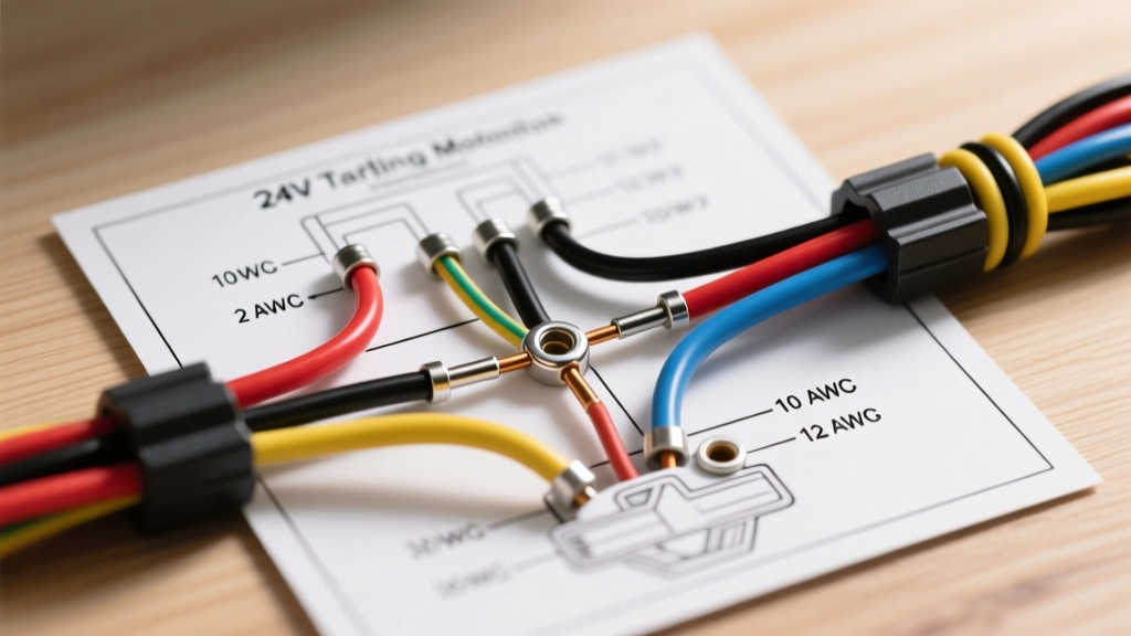
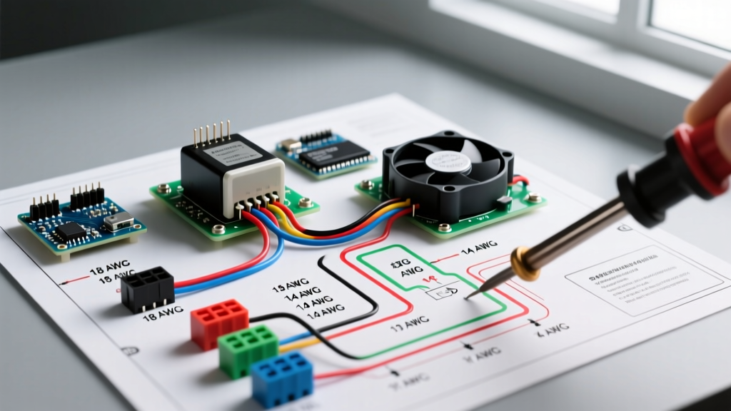
When upgrading a vehicle's cooling system, reading and executing a proper wiring diagram for electric fan relay integration is the difference between a reliable setup and a melted wiring harness. Modern high-CFM electric cooling fans, such as the SPAL 11-inch dual fans or Flex-a-lite Black Magic series, routinely draw between 25 and 40 amps under peak startup load. Routing this amperage directly through a dashboard switch, an ECU driver, or a basic thermal probe will instantly overload the control circuit, leading to catastrophic failure.
A relay acts as a heavy-duty, remote-controlled switch. It allows a low-amperage trigger circuit (typically under 1 amp) to safely control a high-amperage power circuit directly from the battery. As of 2026, the market is flooded with substandard relays; therefore, this installation planning guide focuses on automotive-grade ISO Mini relays, precise wire gauge selection, and advanced flyback voltage protection to ensure your cooling system operates flawlessly in extreme engine bay temperatures.
Core Components for a Modern 12V Fan Relay Harness
Before cutting a single wire, you must source the correct components. Do not compromise on wire insulation or relay quality.
- The Relay: Bosch 0332014150 (40A, 12V, 4-Pin ISO Mini). A genuine Bosch unit costs between $8 and $12. Avoid $2 counterfeits, which often use copper-clad aluminum (CCA) internal contacts that pit, arc, and weld shut under high inductive loads.
- Power Wire: 10 AWG TXL (Thin-wall cross-linked) wire. TXL is rated for 125°C continuous engine bay heat, unlike standard PVC wire which becomes brittle and melts at 90°C.
- Control Wire: 16 AWG GXL or TXL wire for the trigger circuit.
- Primary Protection: 40A MAXI blade fuse or a 40A Mega fuse, mounted within 18 inches of the battery positive terminal.
- Secondary Protection: 5A ATO fuse for the ignition-switched control circuit.
- Suppression: 1N4007 Flyback Diode to protect sensitive ECU triggers from Back-EMF.
The Standard 4-Pin ISO Mini Relay Pinout
Understanding the DIN 72552 standard pin numbering is critical when interpreting any wiring diagram for electric fan relay setups. The Bosch 0332014150 uses the following configuration:
| Pin Number | Function | Wire Gauge | Connection Point |
|---|---|---|---|
| 30 | Common (Power In) | 10 AWG | Battery Positive (via 40A Fuse) |
| 87 | Normally Open (Power Out) | 10 AWG | Electric Fan Positive Terminal |
| 86 | Coil Power (Trigger In) | 16 AWG | 12V Ignition Source (via 5A Fuse) |
| 85 | Coil Ground (Trigger Out) | 16 AWG | Thermostat Switch / PWM Controller / ECU |
Step-by-Step Wiring Diagram for Electric Fan Relay Execution
Follow this precise execution flow to build a harness that meets automotive circuit protection standards and minimizes voltage drop.
- Main Power Feed: Run 10 AWG TXL wire from the battery positive terminal to a 40A MAXI fuse holder. Mount the fuse holder as close to the battery as possible to protect the entire downstream cable.
- Relay Power In (Pin 30): Continue the 10 AWG wire from the fuse holder to Pin 30 on the relay socket.
- Relay Power Out (Pin 87): Run a new 10 AWG wire from Pin 87 to the positive terminal of the electric fan. If running dual fans, use a sealed distribution block to split the 10 AWG feed into two 12 AWG drops for the individual fans.
- Fan Grounding: Ground the fan negative terminal directly to the chassis or engine block using a dedicated 10 AWG ground strap. Do not rely on the fan mounting bolts for the primary electrical ground.
- Control Circuit Power (Pin 86): Tap into a 12V ignition-switched source (e.g., the AC clutch fuse or a dedicated accessory fuse). Run 16 AWG wire through a 5A inline ATO fuse to Pin 86. This ensures the fans cannot run if the key is off, preventing battery drain.
- Control Circuit Trigger (Pin 85): Run 16 AWG wire from Pin 85 to your chosen trigger mechanism (thermal switch, manual dashboard toggle, or PWM controller ground output).
Advanced Integration: PWM Controllers vs. Binary Thermostats
When planning your trigger mechanism, you must decide between traditional binary switching and modern Pulse Width Modulation (PWM). This decision fundamentally alters how you wire Pin 85.
| Feature | Binary Thermostat (e.g., Derale 16749) | PWM Controller (e.g., SPAL PWM-V3) |
|---|---|---|
| Operation | 100% ON or 100% OFF based on a fixed temp threshold. | Variable duty cycle (20% to 100%) to maintain exact target temp. |
| Amperage Spikes | High. Full startup surge (35A+) hits every time it cycles. | Low. Soft-starts fans and maintains lower average amperage. |
| Wiring Requirement | Standard 4-pin relay wired exactly as diagrammed above. | PWM unit acts as the relay. Heavy-duty 40A+ solid-state internal switching. External relay often bypassed. |
| Cost (2026) | $35 - $50 | $140 - $180 |
Expert Note: If you are using a high-end PWM controller like the SPAL PWM-V3, the controller itself contains heavy-duty solid-state relays. You will wire the 10 AWG power directly from the battery fuse to the PWM unit, and from the PWM unit to the fans, entirely eliminating the need for an external mechanical Bosch relay.
Common Failure Modes: Flyback Voltage and Voltage Drop
Even with a perfect physical layout, ignoring electrical physics will destroy your vehicle's electronics. Here are the two most common edge cases in fan relay installations.
1. Flyback Voltage (Back-EMF) Spikes
A relay coil is an inductor. When the trigger circuit (Pin 85) opens to turn the fan off, the magnetic field inside the relay coil collapses. This generates a reverse voltage spike (Back-EMF) that can exceed 100 volts for a fraction of a millisecond. If Pin 85 is triggered by a modern ECU or a delicate solid-state sensor, this spike will instantly fry the internal driver transistor.
The Fix: Solder a 1N4007 flyback diode directly across the relay socket terminals for Pins 85 and 86. The diode's cathode (marked with a silver stripe) must point toward Pin 86 (12V+), and the anode toward Pin 85 (Ground). This creates a closed loop for the Back-EMF to safely dissipate as heat rather than traveling back into your ECU.
2. Excessive Voltage Drop
Electric fans are highly sensitive to voltage. A fan rated for 2500 CFM at 13.8V may drop to 1800 CFM if it only receives 11.5V. According to standard American Wire Gauge (AWG) resistance charts, 10 AWG wire has a resistance of approximately 1.0 milliohm per foot.
If your battery is in the trunk and the fan is in the engine bay, a 20-foot round-trip wire run yields 20 milliohms of resistance. At a 35A draw, Ohm's Law (V = I x R) dictates a 0.7V drop. The fan receives 13.1V, which is acceptable. However, if you mistakenly use 14 AWG wire (2.5 milliohms/ft), the drop increases to 1.75V, starving the fan and causing the relay contacts to overheat due to prolonged high-resistance arcing. Always verify your wire gauge against the physical run length, and source high-quality relays from established distributors like Mouser Electronics to guarantee contact material integrity.
Crimping and Termination Standards
Do not use cheap stamped-and-formed open-barrel crimpers for the relay socket. Use a proper Deutsch DT series or Metri-Pack 280 series sealed connector system for the fan side to prevent moisture ingress. For the relay socket, use a ratcheting crimper designed for insulated terminals, and always seal the back of the socket with dielectric grease and a silicone boot to prevent engine bay corrosion from creating high-resistance faults over time.