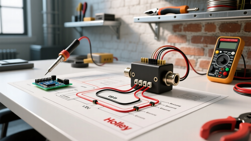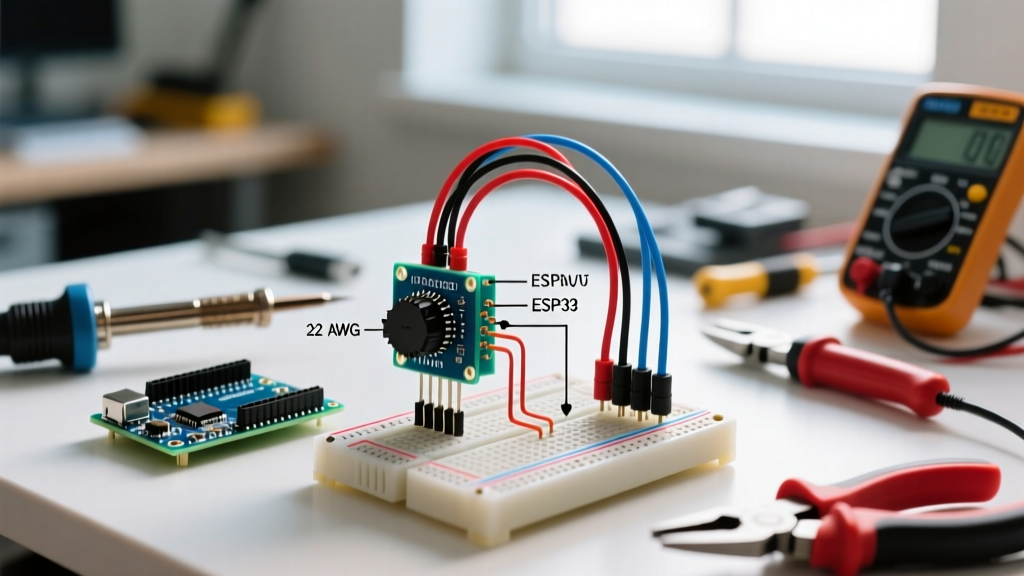

Introduction to Heavy-Duty Potentiometer Safety and Compliance
When hobbyists think of potentiometers, they typically picture small 10kΩ carbon-film components on a 5V breadboard. However, in industrial and commercial electrical environments, a wiring diagram for potentiometer integration involves high-wattage, wirewound, and multi-turn precision components used for motor speed control, industrial lighting dimming, and HVAC damper actuation. These heavy-duty components operate in high-voltage or high-current control circuits where improper wiring can lead to catastrophic arc flashes, thermal fires, and severe National Electrical Code (NEC) violations.
As of 2026, electrical inspectors are increasingly scrutinizing control panel layouts and field-wired control circuits. According to the NFPA 70 (National Electrical Code), control circuits must be properly protected against overcurrent, and all field wiring must be housed in appropriately rated enclosures. This guide provides a deep dive into the safety-critical aspects of potentiometer wiring, bridging the gap between theoretical circuit diagrams and real-world code compliance.
Decoding the Wiring Diagram for Potentiometer Circuits
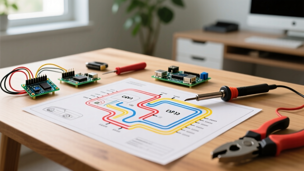
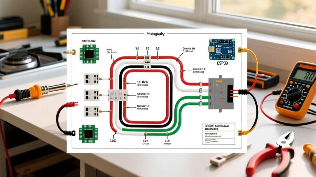
A standard potentiometer features three terminals: Terminal 1 (Counter-Clockwise / CCW), Terminal 2 (The Wiper), and Terminal 3 (Clockwise / CW). How you wire these terminals dictates both the circuit functionality and its inherent safety profile.
1. The Voltage Divider Configuration (3-Terminal)
In a voltage divider setup, the full input voltage is applied across Terminals 1 and 3, while the output signal is drawn from Terminal 2 (the wiper). This is standard for VFD (Variable Frequency Drive) speed reference signals and PLC analog inputs. Safety Note: Because the wiper carries only a low-current signal (typically 4-20mA or 0-10V), the primary safety concern here is signal isolation and shielding to prevent electromagnetic interference (EMI) from adjacent high-voltage power lines.
2. The Rheostat Configuration (2-Terminal Failsafe)
When a potentiometer is used to vary resistance in series with a load (such as a DC motor field winding or a heating element), it acts as a rheostat. The most critical safety rule in this wiring diagram for potentiometer setups is the Wiper Failsafe Tie.
Critical Safety Rule: Never leave Terminal 3 floating when wiring a rheostat. Always physically wire Terminal 3 directly to Terminal 2 (the wiper). If the wiper loses mechanical contact with the resistive track due to vibration or wear, a floating terminal creates an open circuit. In inductive loads, an open circuit causes a massive voltage spike (V = L × di/dt) that will arc across the wiper gap, destroying the component and potentially igniting nearby combustible materials. Tying the terminals ensures the circuit defaults to maximum resistance rather than an open state.
NEC Code Compliance and Enclosure Standards
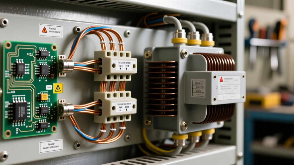
Mounting a bare wirewound potentiometer on a panel without proper enclosure is a direct violation of safety codes. The NEC and OSHA electrical safety standards mandate that all exposed current-carrying parts operating over 50V must be guarded.
Selecting the Right NEMA Enclosure
Potentiometers generate significant heat. Wirewound models, in particular, rely on ambient air for cooling. When selecting an enclosure, you must balance environmental protection with thermal dissipation.
| NEMA Rating | Application Scenario | Thermal & Code Considerations |
|---|---|---|
| NEMA 1 | Indoor control panels, clean rooms | Requires ventilation louvers to prevent heat trapping; standard for most VFD control pots. |
| NEMA 4 | Outdoor washdown, food processing | Watertight. Requires internal thermal calculations; may need an aluminum mounting plate to act as a heatsink. |
| NEMA 12 | Industrial manufacturing, dusty areas | Dust-tight. Potentiometer shaft seals must be inspected annually to prevent ingress of conductive dust. |
| NEMA 4X | Marine, chemical processing | Corrosion-resistant. Fiberglass enclosures are preferred, but UV degradation must be monitored. |
Overcurrent Protection (NEC Article 240 & 430)
If the potentiometer is part of a motor control circuit, NEC Article 430 dictates that the control circuit must be tapped from the load side of the motor branch-circuit short-circuit and ground-fault protective device. For control circuits drawing less than 5 amps, you must install supplementary fuses (e.g., 2A or 3A time-delay midget fuses) directly in series with the potentiometer’s supply line to protect the delicate wiper track from short-circuit currents.
Wire Gauge Selection and Thermal Derating
A common failure point in industrial panels is the use of undersized wire for high-wattage potentiometer leads. While the control signal might only be 18 AWG, the power leads feeding a 50W wirewound potentiometer must be sized for the full current load plus a 25% safety margin.
Calculating Thermal Derating
Wirewound potentiometers are rated for their nominal wattage at a specific ambient temperature, typically 40°C or 50°C. As the ambient temperature inside an enclosed control panel rises, the component must be thermally derated.
- 40°C to 150°C: Linear derating begins. A 50W pot at 100°C ambient may only safely dissipate 25W.
- Max Hot-Spot Temperature: Usually around 340°C for silicone-coated wirewounds. Exceeding this degrades the insulation, leading to shorted turns and catastrophic track failure.
- Mitigation: Use a potentiometer with a wattage rating at least 2x to 3x your calculated maximum circuit dissipation. If your circuit dissipates 10W, specify a 25W or 50W component.
Step-by-Step Safe Installation Protocol
Follow this precise installation sequence to ensure mechanical integrity and electrical safety:
- LOTO Verification: Perform Lockout/Tagout. Verify zero energy state using a CAT III or CAT IV multimeter across all phases and ground.
- Panel Preparation: Drill the mounting hole using a stepped drill bit to avoid jagged edges that could compromise the potentiometer’s O-ring seal. Deburr the hole thoroughly.
- Mounting and Torque: Insert the potentiometer and secure the dress nut. Critical: Use a calibrated torque wrench. Most industrial pots (like the Ohmite Dividohm series) require exactly 15 to 20 in-lbs of torque on the mounting nut. Over-tightening cracks the ceramic core; under-tightening allows rotational slip.
- Wiring and Termination: Strip wires to exactly 1/4 inch. Use ferrule crimps on all stranded wires before inserting them into the screw terminals. Torque terminal screws to 7-9 in-lbs.
- Anti-Rotation Pin: Engage the anti-rotation pin into the panel hole. If the panel is too thick, use an anti-rotation washer bracket. A spinning potentiometer body will quickly sever the internal wiring.
Common Failure Modes and Edge Cases
Understanding how these components fail allows for better preventative design in your wiring diagrams:
- Wiper Lift-Off: Caused by severe vibration. Solution: Use multi-turn precision pots with wiping contacts that feature higher spring pressure, or add mechanical vibration dampeners to the panel.
- Track Hotspots: Occurs when a high current is drawn from a specific, narrow section of the resistive track repeatedly. Solution: Avoid using the extreme bottom 10% of the potentiometer’s range for high-current loads.
- Galvanic Corrosion: Using copper wire directly on brass terminals in high-humidity environments. Solution: Apply a thin layer of di-electric grease or use tinned copper wire.
2026 Component Pricing and Sourcing Guide
When budgeting for industrial control panel upgrades in 2026, expect the following pricing tiers for high-reliability, UL-listed potentiometers:
- Ohmite Dividohm Series (Heavy Duty Wirewound): Models like the D25K100E (25W, 100Ω) typically range from $65 to $85. These are the gold standard for high-power rheostat applications and feature a vitreous enamel coating for superior moisture resistance.
- Vishay 534 Series (Multi-Turn Precision): 10-turn, 2W precision pots (e.g., 534B1103JC) used for VFD analog references cost between $18 and $28. They offer exceptional resolution and long rotational life (up to 1 million turns).
- Bourns 3590 Series (Wirewound Precision): A cost-effective alternative for 2W to 3W applications, generally priced around $12 to $16, ideal for high-volume OEM panel builds.
Frequently Asked Questions (FAQ)
Can I use a standard carbon-film potentiometer for a 120V AC lighting dimmer circuit?
No. Standard carbon-film pots are typically rated for low-voltage DC or low-current signal applications. For 120V AC line-voltage dimming, you must use a UL-recognized, heavy-duty wirewound potentiometer specifically rated for AC line voltage, housed in a NEMA-rated enclosure, and protected by a properly sized thermal fuse.
Does the NEC require a specific wire color for potentiometer control signals?
While the NEC does not mandate a universal color for analog control signals, NFPA 79 (Electrical Standard for Industrial Machinery) recommends using yellow for control circuits that remain energized when the main disconnect is off, and red for standard AC control circuits. For DC analog signals (0-10V), blue or blue-with-white-trace is the industry standard to differentiate them from power wiring.
How do I test a wired potentiometer for safety before energizing the panel?
Before applying power, disconnect the potentiometer from the sensitive load (e.g., the VFD or PLC). Use a multimeter in resistance mode to measure between the wiper and the grounded chassis to ensure there are no internal short circuits. Then, measure the resistance across the active terminals while slowly turning the shaft to check for infinite spikes or dead spots, which indicate a damaged resistive track.