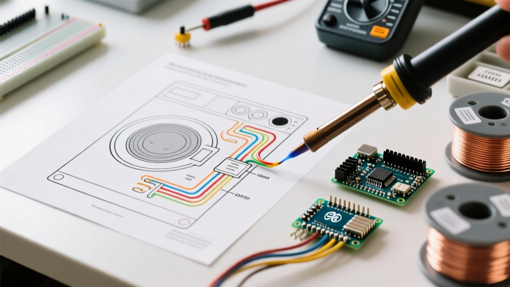

Decoding the Schematic: Locating Your GE Dryer Wiring Diagram
When a General Electric (GE) electric dryer fails to produce heat or refuses to tumble, guessing which component has failed is a waste of time and money. The most efficient diagnostic path is using the factory wiring diagram. Unlike generic appliance repair guides, the specific wiring diagram for GE dryer models maps out the exact 240V and 120V circuits, control board logic, and safety interlocks unique to your machine.
In most GE models (such as the GTD72 series or the GUD27 Unitized Spacemaker), the schematic is not found in the user manual. Instead, look for a folded mini-manual hidden inside the lower front kick panel, tucked behind the rear console access panel, or folded inside the top control console. This document contains the ladder logic diagram, the timer sequence chart, and the component location map.
Essential Tools for 240V Appliance Diagnostics
Before touching a single wire, you must verify that the power is disconnected at the breaker panel. Electric dryers operate on 240V, which is lethal. Once the unit is unplugged or the breaker is locked out, you will need specific diagnostic tools:
- True RMS Digital Multimeter: A standard multimeter is fine for continuity, but for live voltage testing (when tracing the 240V supply), a True RMS meter like the Klein Tools MM400 (approx. $45) or Fluke 115 ensures accurate readings on non-linear loads.
- Wire Piercing Probes: These allow you to test for voltage at the terminal block or motor harness without stripping insulation or back-probing delicate connector pins.
- Appliance Multimeter Adapters: Useful for bridging spade connectors on components like the high-limit thermostat while maintaining circuit continuity.
Power Supply Verification: The Terminal Block Matrix
The first node on any GE dryer wiring diagram is the power entry point. GE dryers are typically sold without a power cord, meaning the terminal block wiring depends on whether your home uses a 3-prong or 4-prong outlet. According to the National Electrical Code (NEC) Article 250, modern installations require a 4-prong setup to separate the equipment ground from the neutral.
Pro-Tip: Wire Gauge Verification
Inspect the terminal block wires. They must be 10 AWG copper to handle the 30-amp circuit requirement. If you find 12 AWG or aluminum wiring on a 30A breaker, this is a severe fire hazard and an NEC violation that must be corrected before proceeding with component troubleshooting.
| Terminal Block Prong | Wire Color (4-Prong) | Expected Voltage (Live Test) | Diagram Destination |
|---|---|---|---|
| L1 (Left) | Black (Hot) | 120V (to Neutral), 240V (to L2) | Timer / Control Board / Motor |
| L2 (Right) | Red (Hot) | 120V (to Neutral), 240V (to L1) | Heater Circuit / Motor Centrifugal Switch |
| Neutral (Center) | White (Neutral) | 0V (Reference), 120V (to L1/L2) | 120V Control Circuits / Drum Light |
| Ground (Chassis) | Green (Ground) | 0V | Dryer Frame / Chassis |
Troubleshooting the No-Heat Failure Mode
The most common reason for consulting a wiring diagram for GE dryer models is a 'no-heat' condition. The heating circuit is a series loop that relies on multiple safety switches. If any single switch opens, the 240V supply to the heating element is broken.
Step 1: Tracing the Thermal Fuse and High-Limit Thermostat
Follow the L2 (Red) wire on your schematic. It typically routes first to the Thermal Fuse (often part number WE4M533 or WE4X584). This is a one-time, non-resettable safety device designed to blow if the exhaust vent is restricted and internal temperatures exceed 250°F. Set your multimeter to continuity (ohms). A good fuse will read less than 0.5 ohms. An open circuit (OL) means the fuse has blown.
Next, trace the wire to the High-Limit Cycling Thermostat (part number WE4M532 on electronic models, or WE4X584 on mechanical). Unlike the thermal fuse, this component is designed to cycle open and closed. At room temperature, it should show continuity. If it reads open (OL) while cold, the thermostat has failed and must be replaced.
Step 2: The Motor Centrifugal Switch and Heating Element
Many DIYers miss the centrifugal switch located inside the drive motor assembly. The wiring diagram shows that L2 power must pass through this switch before reaching the heating element. This is a critical safety feature: if the motor stops spinning (e.g., a broken drum belt), the centrifugal switch opens, cutting power to the heater to prevent a fire. If your drum is tumbling but there is no heat, the centrifugal switch is likely closed, allowing you to move on to testing the Heating Element (commonly part number WE11M23).
Disconnect the wires from the element terminals and measure the resistance. A healthy GE heating element should read between 8 and 15 ohms. A reading of OL indicates a broken internal coil. Also, test for continuity between each terminal and the metal heater housing; any reading other than OL indicates a short to ground, requiring immediate replacement.
Advanced Diagnostics: Electronic Control Boards and Thermistors
As of 2026, newer GE dryer models utilize electronic control boards (PCBs) rather than mechanical timers. These boards rely on thermistors to monitor exhaust temperature. If your schematic shows a thermistor (part number WE4M532) connected to the PCB, you must test its resistance-to-temperature curve.
At standard room temperature (70°F / 21°C), a GE thermistor should read approximately 50 kΩ (50,000 ohms). If the thermistor reads shorted (0 ohms) or open (OL), the PCB will default to a safety mode, often displaying an error code and disabling the heater. Replacing the $15 thermistor is vastly cheaper than replacing a $120+ control board. Always test the sensor before condemning the PCB.
Common Mistakes When Reading GE Schematics
- Ignoring the Door Switch Interlock: The wiring diagram clearly shows that the door switch (part number WE1X1192) interrupts both the motor start circuit and, on some models, the heater relay. A broken door switch paddle will prevent the dryer from starting entirely.
- Confusing 120V and 240V Legs: The drum light, timer motor, and electronic display operate on 120V (L1 to Neutral). The heater and main drive motor operate on 240V (L1 to L2). If the drum light works but the dryer won't start, you likely have a blown L2 fuse at the main breaker panel, cutting 240V power while leaving 120V intact.
- Bypassing Safety Limits: Never use a jumper wire to bypass a blown thermal fuse to 'test' the dryer. According to the U.S. Consumer Product Safety Commission (CPSC), clothes dryers are a leading cause of residential fires. Bypassing a thermal fuse removes the last line of defense against a lint-fueled fire.
Conclusion: Trust the Ladder Logic
Troubleshooting a GE electric dryer does not require guesswork. By systematically following the ladder logic on your wiring diagram, verifying your 240V supply at the terminal block, and using a multimeter to check the exact resistance values of the thermal fuse, thermostats, and heating element, you can isolate 95% of all common failure modes. Always prioritize safety, adhere to NEC grounding standards, and rely on OEM part numbers to ensure your appliance operates safely for years to come. For more detailed schematics and official technical bulletins, consult the GE Appliances Support Portal directly with your specific model number.