
Anatomy of a Modern Access Control Circuit
Designing and installing a reliable physical security infrastructure requires a deep understanding of low-voltage electronics and power distribution. When reviewing a standard wiring diagram for door access control, the most common points of failure are rarely the controllers or readers themselves; instead, they stem from improper wire gauge selection and misinterpreted color codes. As security systems transition from legacy unencrypted protocols to advanced encrypted standards in 2026, the physical cabling layer must be treated with the same rigor as network infrastructure.
A complete access control circuit typically comprises five core components: the access controller (e.g., ZKTeco C3-400 or HID VertX V1000), the credential reader (e.g., HID Signo 40), the locking hardware (magnetic lock or electric strike), the request-to-exit (REX) sensor, and the central power supply (usually a 12V DC or 24V DC linear or switching power supply with battery backup). Connecting these components requires navigating a mix of data signals, high-current lock actuations, and dry contact closures.
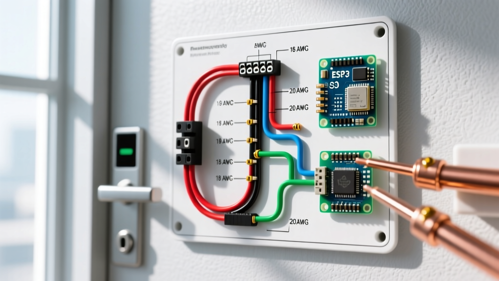
Wire Gauge Selection Matrix for Access Control
Voltage drop is the silent killer of access control systems. A magnetic lock that requires 12.0V DC to hold securely will begin to chatter, overheat, and eventually fail to release if the voltage at the lock drops below 10.5V DC due to undersized cabling. According to the National Electrical Code (NFPA 70), low-voltage Class 2 and Class 3 circuits must still adhere to strict ampacity and voltage drop guidelines to prevent fire hazards and ensure operational integrity.
The following matrix provides exact wire gauge requirements based on distance and current draw for 12V DC and 24V DC systems.
| Circuit Type | Typical Current | Distance (ft) | Recommended AWG (12V DC) | Recommended AWG (24V DC) |
|---|---|---|---|---|
| Reader Data (Wiegand) | < 100mA | Up to 500 | 22 AWG (Shielded Twisted Pair) | 22 AWG (Shielded Twisted Pair) |
| Reader Data (OSDP / RS-485) | < 100mA | Up to 4,000 | 24 AWG to 18 AWG (STP) | 24 AWG to 18 AWG (STP) |
| Maglock (Fail-Safe) | 0.5A - 1.0A | Up to 50 | 18 AWG | 22 AWG |
| Maglock (Fail-Safe) | 0.5A - 1.0A | 50 - 150 | 16 AWG | 18 AWG |
| Maglock (Fail-Safe) | 0.5A - 1.0A | 150 - 300 | 14 AWG | 16 AWG |
| Electric Strike (Fail-Secure) | 0.2A - 0.4A | Up to 100 | 18 AWG | 22 AWG |
| REX Motion Sensor | < 50mA | Up to 500 | 22 AWG | 22 AWG |
Pro Tip: Always calculate voltage drop using the formula: V_drop = (2 × Length × Wire Resistance per 1000ft × Current) / 1000. For a 100-foot run of 18 AWG copper wire (6.385 ohms/1000ft) carrying 0.5A to a 12V maglock, the drop is 0.63V, leaving 11.37V at the lock—well within the safe operating tolerance.
Industry Standard Color Codes: Wiegand vs. OSDP
One of the most frustrating aspects of interpreting a wiring diagram for door access control is the lack of universal standardization across all manufacturers. However, the industry has largely coalesced around specific color codes for the two dominant data protocols: Wiegand and OSDP (Open Supervised Device Protocol).
Legacy Wiegand (26-bit / 34-bit / HID H10301)
While Wiegand is being phased out due to its lack of encryption, millions of doors still utilize it. The standard 6-conductor or 8-conductor jacketed cable typically follows this color scheme:
- Red: DC Power (+12V DC or +5V DC, depending on reader spec)
- Black: Ground (0V / Common)
- Green: Data 0 (D0 / Data Low)
- White: Data 1 (D1 / Data High)
- Orange: Reader LED Control (Optional)
- Blue: Reader Beeper Control (Optional)
- Brown / Violet: Tamper Switch (Optional)
Modern OSDP (RS-485 Encrypted)
As documented by the Security Industry Association (SIA), OSDP utilizes RS-485 differential signaling, allowing for much longer cable runs and two-way encrypted communication. The color code for OSDP is distinctly different to prevent installers from accidentally wiring it as Wiegand:
- Red: DC Power (+12V DC)
- Black: Ground (0V / Common)
- Green: RS-485 A (Data +)
- White: RS-485 B (Data -)
- Shield (Drain Wire): Must be terminated at the controller chassis ground ONLY to prevent ground loops.
Critical Warning: Never connect the shield drain wire at both the reader and the controller. Doing so creates a ground loop, which will introduce 60Hz AC hum into the data lines, causing OSDP communication timeouts and random reader reboots.
Lock Hardware Wiring: Fail-Safe vs. Fail-Secure
The locking hardware dictates how the controller's relay must be configured (Normally Open vs. Normally Closed) and influences the wiring diagram for door access control significantly.
Fail-Safe (Magnetic Locks / Electromagnetic Locks)
Magnetic locks, such as the Securitron M680 series, require continuous power to remain locked. They are wired to the Normally Open (NO) and Common (COM) terminals of the controller's lock relay. When a valid credential is presented, the controller energizes the relay, closing the NO circuit, which cuts power to the maglock, allowing the door to open. Fire codes universally require fail-safe hardware on primary egress paths.
Fail-Secure (Electric Strikes)
Electric strikes, like the HES 1006 series, remain locked when power is removed and unlock when power is applied. These are wired to the Normally Closed (NC) and Common (COM) terminals. When a credential is read, the controller breaks the NC circuit, cutting power and allowing the strike to remain locked—wait, no. Let's clarify: Fail-secure strikes unlock when power is applied. Therefore, they are wired to the NO and COM terminals. When the relay triggers, it sends power to the strike, releasing the keeper. (Note: Always verify the specific strike's manual, as some solenoids operate inversely).
Back-EMF Suppression: The Most Overlooked Step
When a magnetic lock or electric strike de-energizes, the collapsing magnetic field inside the solenoid generates a massive reverse voltage spike known as Back-Electromotive Force (Back-EMF). This spike can easily exceed 100V DC for a fraction of a millisecond, traveling back up the power line and destroying the controller's relay contacts or frying the microprocessor.
To prevent this, every wiring diagram for door access control must include a flyback diode or a Metal Oxide Varistor (MOV) installed directly across the lock's positive and negative terminals at the lock housing (not at the controller).
- Diode Selection: Use a 1N4004 or 1N5408 rectifier diode. The silver band (cathode) must point toward the positive (+) voltage source.
- MOV Selection: If using an AC strike or a bidirectional DC circuit, use a bidirectional MOV (e.g., 24V AC/DC rating) to clamp the voltage spike safely.
Expert Troubleshooting Framework
Even with perfect adherence to the wiring diagram for door access control, field conditions can introduce anomalies. Use this framework to diagnose complex issues:
- Ghost Reads / Data Corruption: If the controller registers random credentials or fails to read valid cards, check for AC interference. Wiegand and OSDP data cables must maintain a minimum 12-inch separation from 120V/240V AC lines. If crossing is unavoidable, cross at a strict 90-degree angle.
- Lock Chatter (Maglock buzzing): This is almost always a voltage drop issue. Measure the voltage at the lock terminals while the door is closed and the lock is engaged. If it reads below 11.0V DC on a 12V system, upgrade the wire gauge by two sizes (e.g., from 18 AWG to 14 AWG) or move the power supply closer to the door.
- Controller Relay Welding: If the door unlocks but will not relock, and the controller shows the relay as 'closed', the internal relay contacts have likely welded together due to Back-EMF arcing. Replace the controller board and install a flyback diode at the lock immediately.
- RS-485 OSDP Timeout: OSDP requires a continuous daisy-chain topology. Star topologies (running individual cables from the controller to multiple readers) will cause signal reflections and communication failures. Furthermore, ensure 120-ohm termination resistors are installed at the last reader in the RS-485 chain.
For comprehensive low-voltage cabling pathways and support structures, installers should consult the BICSI Telecommunications Distribution Methods Manual (TDMM), which provides the gold standard for physical cable management in commercial security deployments. By respecting wire gauge physics, adhering to protocol-specific color codes, and implementing proper Back-EMF protection, your access control installations will achieve maximum uptime and security compliance.