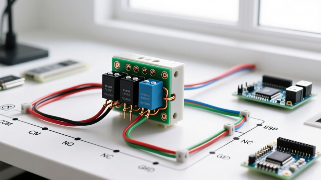

The Strategic Role of the 4-Pin Relay in Modern Circuits
Whether you are integrating high-draw off-road lighting, upgrading an automotive fuel pump, or designing an industrial 12V/24V control panel, the 4-pin relay (Single Pole Single Throw - Normally Open, or SPST-NO) remains the undisputed workhorse of electrical switching. However, skipping the installation planning phase is the primary reason DIYers experience melted harnesses, blown fuses, or destroyed solid-state control modules.
This guide provides a comprehensive, 2026-updated installation planning framework centered around the standard wiring diagram for 4 pin relay configurations. We will move beyond basic schematics to cover DIN 72552 pinout standards, precise wire gauge matrices, inductive kickback mitigation, and real-world diagnostic metrics.
Decoding the DIN 72552 Pinout Standard
Before cutting a single wire, you must understand the standardized terminal numbering system used by premium manufacturers like Bosch, Littelfuse, and Tyco. Misidentifying the coil terminals from the load terminals is a catastrophic error that will immediately short your power source to ground.
| Terminal (DIN) | Function | Circuit Type | Standard Wire Color | Typical 2026 Gauge |
|---|---|---|---|---|
| 85 | Coil Ground | Control (Low Current) | Black | 18 - 16 AWG |
| 86 | Coil 12V+ Trigger | Control (Low Current) | Yellow / Blue | 18 - 16 AWG |
| 30 | Common (Load Input) | Load (High Current) | Thick Red | 14 - 10 AWG |
| 87 | Normally Open (Load Out) | Load (High Current) | Thick Green / Blue | 14 - 10 AWG |
Expert Insight: Never rely solely on wire colors left by previous installers. Always verify terminal locations using a multimeter. The coil pins (85/86) will show a resistance reading between 60 and 90 ohms, while the load pins (30/87) will read infinite (OL) when the relay is de-energized.
Strategic Component Selection for 2026 Installations
The market for automotive and industrial relays has stabilized significantly by 2026, but quality disparities remain. Avoid unbranded, bulk-bin relays for critical applications. When planning your install, specify components that feature silver-nickel or silver-cadmium oxide contacts to resist arcing and welding under heavy loads.
- Bosch 0332014150 (30A SPST): The gold standard for automotive off-road and auxiliary lighting. Features a robust ISO mini footprint and integrated bracket. Current retail pricing ranges from $7.50 to $9.00.
- Littelfuse ISO Mini 30A: Excellent for under-hood applications where vibration and heat are factors. Fully sealed versions are available for around $4.50 to $6.00.
- Song Chuan 895-1C-C (50A): If your load exceeds 30A (e.g., high-draw winches or large inverters), step up to a 50A heavy-duty SPST relay. Expect to pay $12.00 to $15.00.
For deeper technical specifications on contact materials and coil sensitivities, refer to the Littelfuse Automotive Relays catalog or the comprehensive Electronics Tutorials Relay Guide.
The Core Wiring Diagram for 4 Pin Relay Setups
A proper installation divides the wiring into two entirely separate circuits: the Control Circuit and the Load Circuit. The relay acts as the galvanic isolation bridge between them.
Phase 1: The Low-Current Control Circuit (Coil)
- Trigger Source: Run an 18 AWG wire from your switch, BCM (Body Control Module), or ECU output to Pin 86. If triggering from a modern solid-state automotive module, ensure the trigger signal can supply at least 150mA (the typical coil draw).
- Ground Path: Run an 18 AWG wire from Pin 85 to a clean, bare-metal chassis ground. Use a ring terminal and secure it with a stainless steel bolt. Do not daisy-chain this ground with high-current accessories.
Phase 2: The High-Current Load Circuit (Switch)
- Power Feed: Run your primary power wire (sized to the load, see matrix below) directly from the battery positive terminal to Pin 30. Crucial: You must install an inline blade or ANL fuse within 6 inches of the battery terminal.
- Load Output: Run the same gauge wire from Pin 87 to the positive terminal of your accessory (light bar, fuel pump, compressor).
- Accessory Ground: Ground the accessory directly to the chassis. Do not route the high-current ground back through the relay.
Wire Gauge and Fuse Sizing Matrix
Undersized wiring is the leading cause of relay harness fires. The following matrix assumes a standard 12V automotive system with a maximum wire run (round trip) of 20 feet. For longer runs, step up one AWG size to mitigate voltage drop.
| Max Continuous Load | Recommended Wire Gauge (AWG) | Required Inline Fuse | Typical Application |
|---|---|---|---|
| 10 Amps | 16 AWG | 15A ATO | LED Light Pods, Horns |
| 15 Amps | 14 AWG | 20A ATO | Fuel Pumps, Cooling Fans |
| 20 Amps | 12 AWG | 25A ATO | Single 50" LED Light Bar |
| 30 Amps | 10 AWG | 40A ATO | Compressors, Winch Solenoids |
Advanced Edge Cases: Flyback Diodes and Contact Pitting
To elevate your installation from amateur to professional, you must account for inductive kickback. According to Macromatic's relay terminology guidelines, any coil of wire acts as an inductor. When you cut power to pins 85/86, the collapsing magnetic field generates a reverse voltage spike that can exceed 100V.
Pro-Tech Callout: Protecting Solid-State Triggers
If your trigger signal (Pin 86) originates from an Arduino, a PLC, or a modern vehicle's CAN-bus-controlled BCM, this 100V spike will instantly fry the output transistor. Solution: Solder a 1N4007 flyback diode across pins 85 and 86. The silver stripe on the diode must face Pin 86 (the positive trigger side). This creates a recirculation loop that safely dissipates the spike.
Contact Pitting on the Load Side:
Switching inductive loads (like an air compressor motor) on the 30/87 side causes severe DC arcing when the relay opens. Over time, this melts the silver contacts, causing the relay to weld shut. If you cannot oversize the relay by 50%, install an RC snubber network (a 0.1µF capacitor and 100-ohm resistor in series) in parallel with the load to absorb the arc energy.
Pre-Flight Installation Checklist
Before applying final power, run through this diagnostic checklist to ensure your wiring diagram for 4 pin relay execution is flawless:
- [ ] Coil Resistance Check: Multimeter reads 60-90 ohms across 85 and 86.
- [ ] Isolation Check: Multimeter reads OL (infinite) between 30 and 87, and between any coil pin and load pin.
- [ ] Ground Integrity: Voltage drop test from the battery negative to the relay Pin 85 ground ring terminal reads less than 0.05V under load.
- [ ] Fuse Proximity: Main load fuse is located within 6 inches of the battery positive terminal, protecting the entire length of the Pin 30 feed wire.
- [ ] Relay Mounting: Relay is mounted vertically with the terminals facing downward or sideways to prevent moisture from pooling inside the connector socket.
Final Thoughts on Relay Planning
A relay is only as reliable as the planning that precedes it. By respecting the DIN pinout standards, properly sizing your AWG and fuses, and implementing flyback protection for sensitive trigger circuits, your 4-pin relay installation will deliver years of flawless, maintenance-free operation. Always prioritize high-quality, name-brand components over generic alternatives to ensure contact integrity and coil longevity in harsh environments.