Mastering the 36 Volt Club Car Electric Golf Cart Wiring Diagram
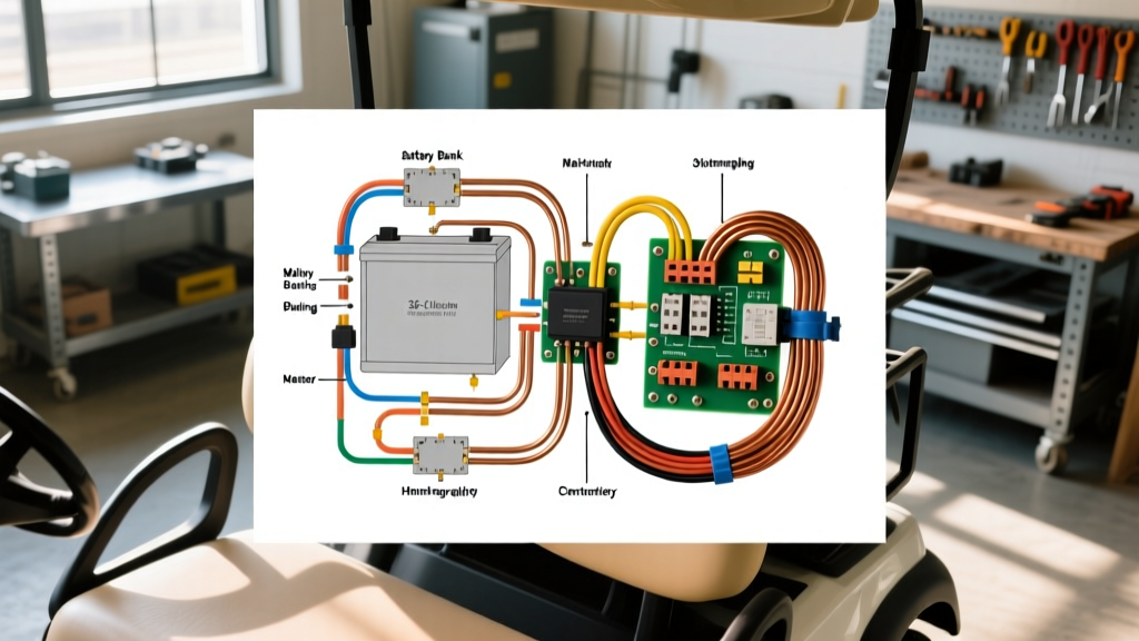
While the electric vehicle market has largely shifted toward 48V and 72V architectures, the 36V Club Car DS remains a legendary, highly customizable platform in 2026. Whether you are restoring a classic 1990s model or breathing new life into a fleet cart, understanding the 36 volt Club Car electric golf cart wiring diagram is the difference between a reliable cruiser and a fire hazard. This installation planning guide bypasses generic advice, focusing strictly on the Advanced DC (ADC) motor and Inductive Throttle System (ITS) configurations that define the most robust 36V setups.
The Core Architecture: High-Current vs. Low-Current Circuits
A critical mistake DIYers make when following a wiring schematic is treating all wires equally. The 36V Club Car architecture is strictly divided into two domains:
- High-Current Drive Circuit: This path carries the raw amperage from the battery bank through the main solenoid, into the motor controller, and out to the drive motor. Peak currents can exceed 350A during heavy acceleration or hill climbs.
- Low-Current Logic Circuit: This includes the Forward/Neutral/Reverse (FNR) switch, the ITS throttle sensor, the solenoid activation coil, and the tow/run switch. These circuits typically operate at under 5A and are highly susceptible to Electromagnetic Interference (EMI).
2026 Component Selection & Wiring Matrix
Before routing a single cable, you must select components that match your performance goals. Below is the definitive component and wire gauge matrix for a modern 36V Club Car DS build utilizing an ADC motor.
| System Component | Recommended 2026 Model | Wire Gauge Requirement | Est. Cost (USD) |
|---|---|---|---|
| Battery Bank (6V x 6) | Trojan T-105 or US Battery US2200 | 4/0 AWG (Interconnects) | $1,500 - $1,850 |
| Motor Controller | Alltrax SR-3648 or Curtis 1204-020 | 2 AWG (High Current) | $380 - $495 |
| Heavy Duty Solenoid | Albright SW180-36V | 2 AWG (Main), 12 AWG (Coil) | $95 - $130 |
| Throttle Sensor (ITS) | Club Car OEM ITS (1996+ DS) | 16 AWG (Shielded Signal) | $45 - $65 |
| FNR Switch Assembly | Club Car OEM 3-Terminal | 12 AWG | $35 - $55 |
Note: When sourcing deep-cycle batteries, always verify the 20-hour Ah rating. According to Trojan Battery's official T-105 specifications, a true 225Ah capacity is essential for maintaining voltage stability under the heavy load of a 36V ADC motor. Alternatively, the US Battery US2200 6V Deep Cycle offers comparable performance with enhanced diamond plate technology for longer cycle life.
Step-by-Step Installation Planning
Phase 1: Battery Bank Configuration and Interconnects
A 36V system requires six 6V batteries wired in series. The physical layout of the Club Car DS battery tray dictates the routing. You must use custom-length 4/0 AWG welding cable with heat-shrink lugs. Do not use pre-cut, generic automotive cables; they are often too long, creating voltage drop and physical clutter that traps battery off-gassing.
- Series Routing: Connect the positive terminal of Battery 1 to the negative of Battery 2, continuing this pattern through Battery 6. The final positive and negative terminals will feed the main cart harness.
- Torque Specifications: Tighten battery terminal bolts to exactly 95-120 in-lbs. Over-torquing soft lead posts will strip the threads, while under-torquing creates micro-arcing and heat buildup.
Phase 2: The Solenoid and Controller Handshake
The solenoid acts as the high-current gatekeeper. In a proper 36 volt Club Car electric golf cart wiring diagram, the main solenoid is placed on the positive B+ line between the battery pack and the controller's B+ terminal.
Critical Information Gain: The Pre-Charge Circuit
Never wire a high-amperage controller without a pre-charge circuit across the main solenoid terminals. This consists of a 470-ohm, 2-watt resistor wired in series with a heavy-duty diode. When the solenoid clicks, the resistor slowly charges the controller's internal capacitors. Without this, the massive inrush current will weld the solenoid's internal copper contacts together, causing a runaway cart.
For the low-current activation side of the solenoid, route a 12 AWG wire from the micro-switch on the accelerator pedal box to the small activation terminal. The other small terminal must be grounded to the controller's negative bus bar, not the cart's frame. Club Car frames are notoriously poor grounds due to paint and corrosion.
Phase 3: Throttle Integration (ITS vs. V-Glide)
If your DS is a 1996 or newer model, it utilizes the Inductive Throttle System (ITS). Unlike the older V-Glide resistive coils, the ITS uses a magnet moving past a Hall-effect sensor to dictate speed. The wiring diagram for the ITS requires three wires: Power (typically 12V or 5V from the controller), Ground, and Signal Output.
EMI Shielding Rule: The ITS signal wire operates in millivolts. If you route this 16 AWG signal wire parallel to your 2 AWG high-current motor cables, the electromagnetic field generated during acceleration will induce 'noise' in the signal wire. The controller will interpret this noise as erratic throttle inputs, causing the cart to surge or enter high-pedal alarm (HPA) safety lockout. Always route logic wires at a 90-degree angle to high-current cables, or use shielded twisted-pair (STP) cable.
Troubleshooting Edge Cases & Failure Modes
The Solenoid 'Click of Death'
A common failure mode occurs when the solenoid clicks audibly, but the cart does not move, and the main cables show full battery voltage on the battery side but 0V on the controller side. Diagnosis: This is rarely a bad solenoid. It is almost always a voltage drop on the activation coil circuit. If the micro-switch or FNR switch contacts are pitted, they may deliver 36V with zero load, but the voltage drops below 28V under the coil's load, failing to pull the heavy internal plunger completely closed. Always test activation voltage under load with the cart jacked up and wheels spinning.
High-Pedal Alarm (HPA) Lockout
Modern controllers like those detailed in Alltrax Inc. DC Motor Controller Guidelines feature a safety lockout if the throttle is depressed before the key switch is turned on. If your wiring diagram places the ITS power feed on a constant 12V source rather than a keyed ignition source, the controller will read throttle input upon boot and disable the motor to prevent runaway scenarios. Ensure the ITS power wire is tied to the keyed ignition circuit or the controller's dedicated switched-power output.
Safety, Code Compliance, and Final Inspection
While golf carts are not strictly bound by the National Electrical Code (NEC) in the same way residential wiring is, adhering to DC safety standards is non-negotiable. Ensure your main positive battery cable is equipped with a 400A Class-T fuse or an ANL fuse mounted within 18 inches of the battery bank's main positive terminal. This protects the cart from catastrophic short circuits in the event of a controller failure or cable chafing.
Finally, verify your Tow/Run switch wiring. In the 'Tow' position, the switch must physically disconnect the controller's main power logic to prevent the motor's regenerative braking (which acts as a generator when coasting) from feeding voltage back into a dead controller. Failing to wire the Tow/Run switch correctly is the leading cause of controller destruction during towing or long-term storage.
By treating the 36 volt Club Car electric golf cart wiring diagram as a precise engineering blueprint rather than a simple suggestion, you ensure a build that delivers reliable torque, maximizes battery lifespan, and eliminates the electrical gremlins that plague amateur installations.