
Understanding the 3 Wire Electric Stove Wiring Diagram
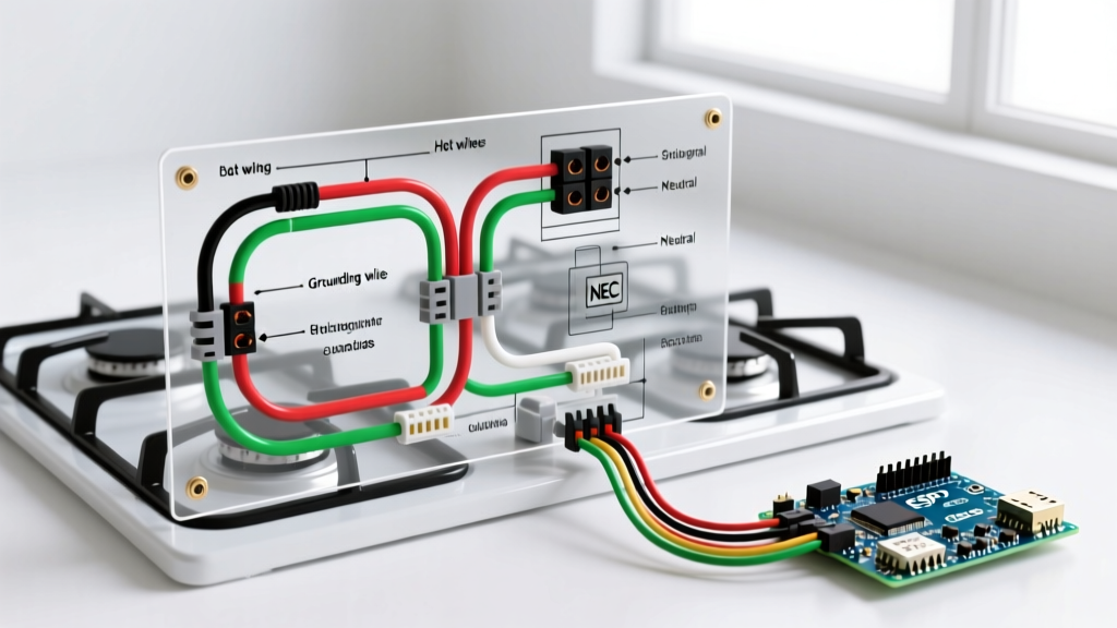
Wiring an electric range requires a precise understanding of voltage requirements, wire gauge limitations, and National Electrical Code (NEC) standards. While modern construction mandates 4-wire setups for new installations, millions of older homes still utilize a 3 wire electric stove wiring diagram configuration. In a 3-wire system, the circuit provides two 120V hot legs (L1 and L2) to deliver 240V for the heating elements, alongside a single combined wire that serves as both the neutral (for 120V components like clocks and oven lights) and the equipment grounding conductor.
Transitioning between 3-prong and 4-prong configurations is one of the most common pitfalls for DIYers and junior electricians. Misinterpreting the color codes or using the wrong cable type can lead to severe shock hazards, destroyed control boards, or electrical fires. This comprehensive reference guide breaks down the exact wire gauges, cable types, color codes, and terminal block procedures required to safely wire a 3-prong electric stove.
Wire Gauge and Cable Selection for 50-Amp Range Circuits
Electric stoves typically require a dedicated 50-amp, 240-volt circuit. Selecting the correct wire gauge is non-negotiable to prevent voltage drop and thermal overload. According to the National Electrical Code (NFPA), the minimum wire sizes for a 50-amp breaker are:
- 6 AWG Copper: The standard for modern residential branch circuits. Rated for up to 55 amps in standard THHN/THWN insulation, making it perfectly suited for a 50A breaker.
- 4 AWG Aluminum: Required if you are using aluminum conductors, as aluminum has higher resistance and requires a larger cross-sectional area to carry the same current safely.
The Critical Difference: SE Cable vs. NM-B (Romex)
One of the most dangerous mistakes in 3-wire stove wiring is using standard 6/3 NM-B (Romex) cable and attempting to use the bare copper wire as a neutral. This is a severe NEC violation. In NM-B cable, the bare wire is strictly an equipment ground and is never permitted to carry continuous unbalanced return current.
For a legitimate 3-wire range circuit, you must use Type SE (Service Entrance) Style R cable. In older SE Style R cable, the bare concentric wire is permitted by NEC Article 338.10(B) to serve as the grounded conductor (neutral) in existing installations, provided it is properly bonded to the appliance frame. Alternatively, if you are running a new circuit today, you must run a 4-wire cable (6/3 NM-B with Black, Red, White, and Bare) and install a 4-prong NEMA 14-50R receptacle.
3-Wire Color Code Reference and Terminal Mapping
When working with a 3-prong NEMA 10-50P cord and a 3-wire SE cable, the color coding dictates the terminal block connections. Below is the definitive mapping for standard 3-wire range pigtails.
| Wire Color (Cord) | SE Cable Color | Terminal Block Label | Function & Voltage |
|---|---|---|---|
| Black | Black (Insulated) | L1 (Left Hot) | 120V to Neutral / 240V to L2 |
| Red | Red (Insulated) | L2 (Right Hot) | 120V to Neutral / 240V to L1 |
| White (Center) | Bare (Style R SE) | N / Center Terminal | Neutral Return & Frame Ground Bond |
Expert Note: Never assume the center wire on a 3-prong pigtail is white. Many heavy-duty range cords use a gray or ribbed center wire. Always identify the center conductor as the neutral/ground bond point, regardless of its specific color or texture.
Step-by-Step Terminal Block Connection Guide
Connecting a 3-prong pigtail to the stove's terminal block requires precision, proper strain relief, and the mandatory installation of a bonding strap. Follow these steps to ensure a safe, code-compliant connection.
Step 1: Access the Terminal Block and Remove the 4-Wire Bond
Remove the metal access cover on the back of the stove. If the stove was previously configured for a 4-prong outlet, the neutral terminal (center) will be isolated from the metal chassis. You must locate the bonding strap or bonding jumper wire (usually a small copper tab or a green wire with a ring terminal). Connect this strap between the center neutral terminal and the metal chassis ground screw. This is what allows the neutral wire to also serve as the safety ground in a 3-wire system.
Step 2: Install the Strain Relief Connector
Feed the 3-prong pigtail through the knockout hole in the back panel. Install a 3/4-inch or 1-inch metal strain relief connector (depending on your cord diameter) and tighten the locknut. This prevents the heavy cord from pulling on the terminal screws if the stove is moved.
Step 3: Terminate the Conductors
Strip exactly 3/4 inch of insulation from the Black, Red, and White wires. Connect them to the terminal block as follows:
- Black Wire: Connect to the L1 (left) terminal.
- Red Wire: Connect to the L2 (right) terminal.
- White/Center Wire: Connect to the N (center) terminal.
Step 4: Apply Proper Torque
Loose terminal connections are the leading cause of electrical fires in high-draw appliances. Using a calibrated torque screwdriver, tighten the terminal screws to the manufacturer's specification, typically between 35 and 50 inch-pounds. If the exact spec is unavailable, ensure the wire is seated deeply under the screw head or terminal plate with no exposed copper outside the block, and tighten firmly until the screwdriver clicks or the wire cannot be pulled free with a solid tug.
NEC Code Compliance: The 3-Wire Exception
Since the 1996 NEC update (and reinforced in subsequent cycles up to the current code), all new installations require a 4-wire circuit with a separate equipment grounding conductor. However, the NEC recognizes the financial and structural burden of retrofitting older homes.
Under NEC Article 250.140 Exception 1, you are legally permitted to use a 3-wire setup and bond the neutral to the frame for existing branch circuits where a separate equipment ground is not present. If you are simply replacing an old stove with a new one in a home that already has a 3-prong NEMA 10-50R receptacle, you must purchase a 3-prong range cord and install the bonding strap. For a detailed visual breakdown of cord adaptations, the Electrical 101 Range Wiring Guide provides excellent supplementary diagrams.
Common Failure Modes and Troubleshooting
Even with a correct 3 wire electric stove wiring diagram, specific failure modes can occur over time. Understanding these edge cases will save you hours of diagnostic work.
1. The "Floating Neutral" Destroying Control Boards
Symptom: The stove's digital clock flickers, the oven light burns out instantly, or the main control board shorts out upon turning on a burner.
Cause: In a 3-wire system, the center wire carries the unbalanced 120V return current. If the center terminal screw is loose, or the bonding strap is making poor contact with the chassis, the 120V control circuits lose their reference to ground. This causes the voltage to "float," sometimes spiking to nearly 240V across 120V components, instantly frying the electronic control board.
Fix: Cut power at the breaker. Inspect the center terminal for arcing or melting. Re-terminate the wire, apply anti-oxidant paste if using aluminum SE cable, and torque to spec.
2. Voltage Drop on Long Cable Runs
Symptom: The stove takes significantly longer to preheat, and the heating elements glow dimly or cycle erratically.
Cause: 6 AWG copper is rated for 50 amps, but it is subject to voltage drop over distance. If your electrical panel is more than 80 feet away from the stove receptacle, the voltage at the terminal block may drop below 220V under heavy load.
Fix: Use the Southwire Voltage Drop Calculator to verify your run length. For runs exceeding 90 feet on a 50-amp circuit, you must upsize to 4 AWG copper wire to maintain a voltage drop of less than 3%.
3. Aluminum SE Cable Oxidation
Symptom: Intermittent power loss or a burning smell near the receptacle or terminal block.
Cause: Many older homes were wired with aluminum SE cable. Aluminum expands and contracts more than copper when heated, leading to loose connections over time. It also oxidizes, creating a high-resistance layer that generates intense heat.
Fix: If terminating aluminum wire to the stove's terminal block or a receptacle, you must use an AlumiConn connector or apply a UL-listed anti-oxidant compound (like Noalox) to the stripped wire before tightening. Ensure the terminal block is rated AL/CU (Aluminum/Copper).
Summary Checklist for 3-Wire Installations
- Verify the breaker is a 50-Amp double-pole (240V) breaker.
- Confirm the cable is 6 AWG Copper or 4 AWG Aluminum.
- Ensure the bonding strap is securely installed between the center neutral terminal and the stove chassis.
- Tighten all terminal screws to 35-50 inch-pounds.
- Test the receptacle with a multimeter: L1 to L2 should read ~240V; L1 to Neutral and L2 to Neutral should both read ~120V.
By strictly adhering to these wire gauge requirements, color code mappings, and NEC exceptions, you ensure that your 3-wire electric stove operates safely and efficiently, bridging the gap between legacy home infrastructure and modern appliance demands.