
Introduction: The Hidden Motor in Your Doorbell Circuit
When most homeowners think of smart home upgrades, they rarely consider the electromechanical components hiding inside their walls. However, if you are installing a hardwired smart camera, understanding the wiring diagram for Ring Doorbell systems requires a fundamental grasp of motor control circuits. Specifically, a traditional mechanical doorbell chime relies on a solenoid actuator—a type of linear electric motor—to strike the tone bars.
As of 2026, the Ring Video Doorbell Pro 2 and standard Pro models demand continuous standby power to maintain Wi-Fi connectivity and process AI-driven motion zones. If you wire the device in series with a mechanical chime motor without a proper bypass, the standby current will continuously energize the solenoid coil. This results in a loud 60Hz AC hum, premature coil burnout, and catastrophic failure of the chime unit. This tutorial bridges the gap between smart home installation and traditional motor wiring, providing a comprehensive, electrician-grade guide to integrating your Ring Doorbell with a mechanical solenoid chime safely.
Understanding the Solenoid 'Motor' and Transformer Requirements
In electrical terms, a mechanical doorbell chime is an inductive load. When the doorbell button (a simple momentary switch) is pressed, it completes the low-voltage circuit. Current flows through the copper wire coils of the solenoid motor, generating a magnetic field that pulls a steel plunger to strike the chime bar. When the button is released, the circuit breaks, and a spring returns the plunger.
The Ring Doorbell Pro 2 disrupts this simple circuit by acting as a 'smart switch' that leaks a small amount of continuous current (typically 0.2A to 0.5A) through the circuit to power its internal electronics. Because the solenoid motor is an inductive load, this continuous micro-current can cause the plunger to vibrate rapidly against the core, generating excessive heat and eventually melting the coil's enamel insulation.
Transformer Sizing: The VA Rating Imperative
To prevent voltage sag and motor burnout, your transformer must be sized correctly. Volt-Amps (VA) dictates the total power capacity. According to the NFPA National Electrical Code guidelines for Class 2 circuits, doorbell transformers must be properly rated for the continuous load of modern smart devices.
- Older Homes (Pre-2000): Typically feature 10VA or 16VA transformers (16V AC). These are entirely insufficient for Ring Pro models and will overheat.
- Ring Pro (1st Gen): Requires 16V-24V AC, minimum 20VA (30VA recommended).
- Ring Pro 2 (Current 2026 Standard): Strictly requires 16V-24V AC, 30VA minimum. The 3D bird's-eye motion tracking and advanced radar draw significant peak current.
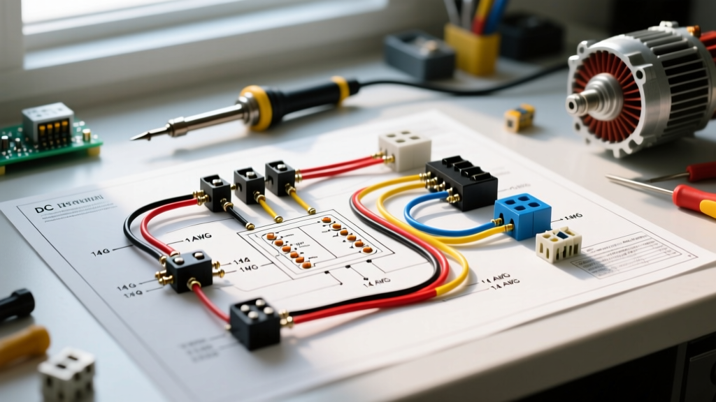
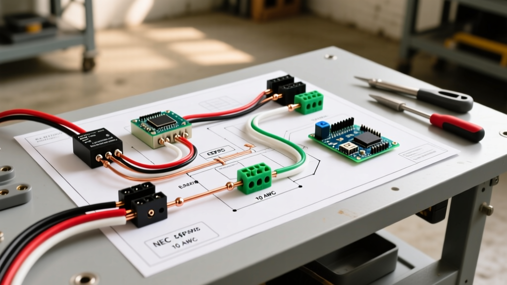
Step-by-Step Wiring Diagram for Ring Doorbell Integration
Before beginning any work, shut off the breaker controlling your doorbell transformer at the main service panel. Verify the power is off using a non-contact voltage tester at the transformer terminals. For comprehensive safety protocols when working near mains voltage, always consult OSHA Electrical Safety Guidelines.
Phase 1: Upgrading and Wiring the Transformer
- Locate the Transformer: Usually found in the attic, basement, or near the main electrical panel.
- Disconnect Mains Power: Remove the 120V AC line, neutral, and ground wires from the old transformer.
- Install the 30VA Transformer: Connect the 120V AC mains to the primary coil terminals. Connect the low-voltage secondary terminals (16V-24V AC) to your existing 18 AWG or 20 AWG solid copper doorbell wires.
- Secure the Ground: Ensure the transformer chassis is bonded to the electrical ground.
Phase 2: The Chime Box and Pro Power Kit (Bypass) Wiring
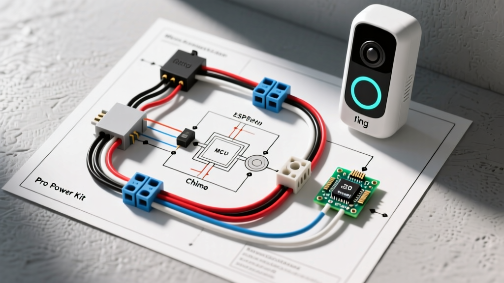
This is the most critical step in the wiring diagram for Ring Doorbell setups. The Pro Power Kit V2 acts as a relay and bypass capacitor, routing standby current around the solenoid motor while allowing the high-current AC pulse to pass through when the doorbell is pressed.
- Remove the Chime Cover: Expose the internal solenoid motor coils and terminal block.
- Identify Terminals: Locate the 'TRANS' (Transformer) and 'FRONT' (Front Door Button) terminals on the chime block.
- Wire the Power Kit:
- Connect the Power Kit's TRANS wire to the chime's TRANS terminal.
- Connect the Power Kit's FRONT wire to the chime's FRONT terminal.
- Install the Bypass Wire (Crucial for Motor Protection): The Pro Power Kit V2 includes a separate bypass wire. Connect this wire directly across the two terminals of the front door solenoid motor coil. This provides the path of least resistance for standby current, completely bypassing the inductive motor coil and eliminating the 60Hz buzz.
Phase 3: The Doorbell Button and Ring Unit
- Connect the two wires at the front door directly to the backplate of the Ring Doorbell Pro 2.
- Polarity does not matter for standard AC doorbell circuits.
- Mount the device, restore power at the breaker, and complete the setup via the Ring app.
Transformer and Solenoid Motor Compatibility Matrix
| Transformer Rating | Voltage Output | Ring Model Compatibility | Solenoid Motor Behavior |
|---|---|---|---|
| 10 VA | 16V AC | None (Will Overheat) | Severe voltage sag; motor fails to strike; transformer burns out. |
| 16 VA | 16V AC | Ring Wired (Standard) | Adequate for basic models; Pro models will cause transformer humming. |
| 20 VA | 16V-24V AC | Ring Pro (1st Gen) | Stable operation if Pro Power Kit bypass is correctly installed. |
| 30 VA | 16V-24V AC | Ring Pro 2 / Pro (All) | Optimal. Solenoid strikes with full force; zero standby coil heating. |
Testing the Chime Solenoid Motor with a Multimeter
If your mechanical chime fails to ring after installing the Ring Doorbell, the solenoid motor coil may have burned out from previous improper wiring. You can test the coil using a digital multimeter set to the Ohms (Ω) resistance setting.
- Disconnect the wires from the solenoid motor terminals.
- Place the multimeter probes on the two coil terminals.
- Normal Reading: A healthy 16V-24V AC solenoid coil typically reads between 5Ω and 15Ω.
- Open Circuit (OL): If the meter reads 'OL' or infinite resistance, the internal copper wire has snapped or melted. The solenoid motor must be replaced.
- Short Circuit (Near 0Ω): Indicates melted insulation between the windings. Replace the unit immediately to prevent transformer damage.
Expert Electrician Tip: Never use a standard 1N4001 diode as a bypass for the Ring Video Doorbell Pro 2. While a diode works for older, simpler smart doorbells by blocking half the AC wave, the Pro 2's advanced radar and Wi-Fi 6 radios require clean, full-wave AC power to prevent reboot loops. Always use the manufacturer-supplied Pro Power Kit V2 for inductive motor bypassing.
Common Failure Modes and Troubleshooting
1. The Chime Motor 'Buzzes' Continuously
Cause: The Pro Power Kit bypass wire is missing, loose, or connected to the wrong terminals. Standby current is passing through the solenoid coil, creating a weak, continuous magnetic field that vibrates the plunger.
Fix: Verify the bypass wire is connected directly across the solenoid coil's physical terminals, not just the chime block's screw terminals.
2. Ring Doorbell Drops Wi-Fi When Chime Rings
Cause: Voltage sag. When the solenoid motor engages, it draws a massive inrush current (up to 1.5A for a fraction of a second). If the transformer is undersized (e.g., 16VA) or the 18 AWG wire run is excessively long (over 100 feet), the voltage at the Ring unit drops below the 3.3V DC internal threshold, causing the camera to reboot.
Fix: Upgrade to a 30VA transformer and ensure wire connections are tight and free of corrosion.
3. Mechanical Chime Sounds 'Weak' or Muffled
Cause: The mechanical linkage is dirty, or the solenoid plunger is binding due to misalignment.
Fix: Clean the plunger shaft with isopropyl alcohol. Do not use petroleum-based lubricants like WD-40, as they attract dust and gum up the linear motor mechanism over time.
Frequently Asked Questions
Can I wire a Ring Doorbell to a DC motor or intercom system?
No. Ring hardwired models are designed strictly for 16V-24V AC (Alternating Current) circuits. Connecting them to a DC (Direct Current) source, such as an older apartment intercom motor circuit or a 12V DC gate transformer, will instantly destroy the internal bridge rectifier and void the warranty. Always verify AC voltage with a multimeter before connecting.
Do I need the Pro Power Kit if I have a digital chime?
Digital chimes do not use a physical solenoid motor; they use a solid-state speaker and a microcontroller. However, they still require a stable voltage to operate. Ring provides a specific 'Digital Chime Adapter' (often a small plug-in module) that must be installed in the digital chime's wiring harness to regulate the current. For more specific model configurations, consult the Ring Official Support Center.
What wire gauge should I use for a new doorbell motor run?
For runs under 100 feet, 18 AWG solid copper wire is the industry standard and perfectly adequate for the 30VA maximum load. For runs exceeding 100 feet, step up to 16 AWG wire to mitigate voltage drop across the inductive solenoid motor circuit.
Conclusion
Treating your doorbell installation as a motor control circuit rather than a simple light switch is the hallmark of a professional smart home integration. By respecting the VA ratings of your transformer, understanding the inductive nature of the solenoid chime motor, and correctly wiring the bypass relay, you ensure your Ring Doorbell Pro 2 operates flawlessly for years to come. Always prioritize safety, verify your circuits, and adhere to local electrical codes when modifying your home's low-voltage infrastructure.