
The Critical Role of Diagrams in Motor Control
Understanding electrical wiring diagram examples is the bridge between theoretical electrical engineering and functional, safe motor control. Whether you are wiring a 1.5 HP single-phase air compressor or integrating a 50 HP 3-phase industrial conveyor, misinterpreting a schematic can lead to catastrophic winding failures, tripped main breakers, or severe arc flash hazards. In 2026, with the industry shifting heavily toward IE4 and IE5 premium efficiency motors, the control circuits have become more sophisticated, demanding precise adherence to manufacturer schematics.
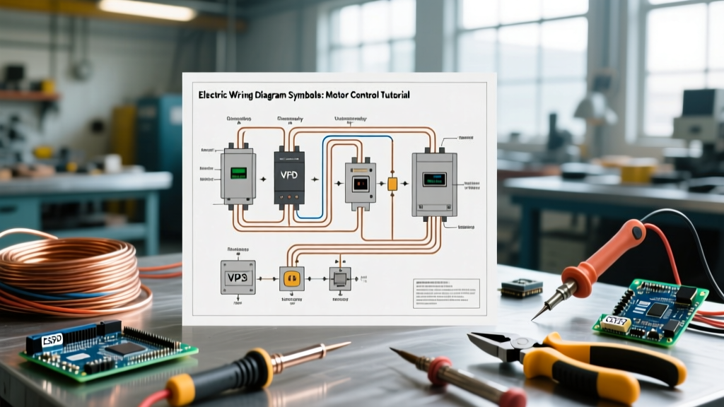
In this tutorial, we will dissect three distinct electrical wiring diagram examples: a single-phase capacitor-start setup, a 3-phase Direct-On-Line (DOL) starter, and a Variable Frequency Drive (VFD) integration. We will focus on specific, real-world hardware to provide actionable depth you cannot find in generic textbooks.
Example 1: Single-Phase Capacitor-Start Motor Wiring
Single-phase motors require a phase shift to generate a rotating magnetic field. The most common industrial variant is the Capacitor-Start/Induction-Run (CSIR) motor. For this example, we will wire a Dayton 1TJE9 (1.5 HP, 115/230V, FLA 16.4/8.2A) motor.
Wiring Flow & Centrifugal Switch Mechanics
- Power Supply to Terminal Block: For 230V operation, connect L1 to Terminal 1 and L2 to Terminal 4. Terminals 2 and 3 are strapped together to configure the internal run windings in series.
- Start Circuit Integration: The start winding is connected in parallel with the run winding but routed through the start capacitor (typically 200-250 µF for this HP rating) and the centrifugal switch.
- Grounding: Bond the green grounding screw to the equipment grounding conductor (EGC). For a 1.5 HP motor on a 20A breaker, a 12 AWG copper EGC is mandatory per NEC Article 250.
Expert Failure Mode Insight: The most common point of failure in this diagram is the centrifugal switch. If the switch contacts weld together or the mechanical spring fatigues, the start winding remains energized after the motor reaches 75% of synchronous speed. Because the start winding is designed with thinner gauge wire and higher resistance, it will overheat past 300°F within seconds, melting the insulation and shorting to the stator core. Always test the switch continuity with a multimeter before sealing the terminal housing.
Example 2: 3-Phase DOL Starter (WEG W22 & Schneider TeSys)
Direct-On-Line (DOL) starting is the simplest method for 3-phase induction motors, applying full line voltage directly to the stator. We will use a WEG W22 IE3 3HP (460V, FLA 4.1A) motor controlled by a Schneider Electric TeSys LE1D09 enclosed starter.
Power Circuit vs. Control Circuit
When analyzing 3-phase electrical wiring diagram examples, you must separate the high-current power circuit from the low-current control circuit.
- Power Circuit: 460V 3-phase enters the disconnect switch, flows through the fuses, into the contactor's L1/L2/L3 terminals, out through T1/T2/T3 into the thermal overload relay (LUCL05FU), and finally to the motor's U/V/W terminals. Torque the M4 terminal screws to exactly 1.2 Nm to prevent micro-arcing from thermal cycling.
- Control Circuit: A step-down transformer drops 460V to 120VAC for the control logic. The circuit flows through the overload relay's normally closed (NC) auxiliary contact (terminals 95-96), through the stop pushbutton (NC), through the start pushbutton (NO), and energizes the contactor coil (A1-A2). A holding contact (13-14) bypasses the start button to maintain the magnetic field.
NEMA vs. IEC Utilization Categories
Choosing the right contactor requires understanding the duty cycle. European IEC standards categorize loads differently than North American NEMA sizing.
| Category | Application | Inrush Multiplier | Typical Use Case |
|---|---|---|---|
| AC-1 | Non-inductive loads | 1.5x FLA | Resistance heaters |
| AC-3 | Squirrel-cage motors | 5x to 7x FLA | Starting, switching off during run |
| AC-4 | Heavy starting/plugging | 7x to 10x FLA | Hoists, cranes, rapid reversals |
Source: Refer to the NEMA MG-1 Standard for comprehensive North American motor sizing classifications.
Example 3: VFD Integration (Yaskawa GA800)
Variable Frequency Drives have become the standard for energy-efficient motor control. Wiring a VFD requires strict attention to cable shielding and separation to prevent electromagnetic interference (EMI). Let us examine wiring a Yaskawa GA800 5HP (460V) drive to a premium efficiency motor.
Line Side, Load Side, and Shielding
VFD electrical wiring diagram examples are uniquely divided into three distinct zones:
- Line Side (Input): Connect L1/L2/L3 to the grid. Crucially, do NOT place standard fuses on the line side without consulting the drive manual; VFDs have massive internal capacitor banks that draw high inrush currents upon power-up. Use semiconductor fuses or a slow-blow Class RK5 fuse sized at 125% of the drive's rated input current.
- Load Side (Output): Connect U/V/W to the motor. You must use specialized symmetrical shielded VFD cable, such as Belden 29304. Standard THHN in conduit acts as an antenna, radiating high-frequency PWM (Pulse Width Modulation) noise that will corrupt nearby PLC signals.
- Shield Termination: The cable shield must be grounded using a 360-degree grounding ring clamp at the VFD enclosure entry point. Pigtailing the shield (twisting it and connecting it to a ground lug) defeats the Faraday cage effect at frequencies above 10 MHz, rendering the shielding useless against common-mode noise.
Real-World Troubleshooting & Edge Cases
Even with perfect wiring, motors fail. According to the U.S. Department of Energy, over 50% of motor failures are electrical, yet many are misdiagnosed as mechanical. Here is how to use your multimeter to diagnose edge cases:
Voltage Unbalance
A voltage unbalance of just 2% between phases can cause a current unbalance of up to 12%, leading to a 15% rise in stator temperature. If your WEG motor is running hot, measure L1-L2, L2-L3, and L3-L1 at the contactor output. If the maximum deviation from the average exceeds 1%, install a phase-monitoring relay (e.g., Macromatic MPD-800) to trip the control circuit before the insulation degrades.
Bearing Fluting from VFDs
If a motor driven by a Yaskawa VFD fails within 12 months with noisy bearings, the culprit is likely common-mode voltage inducing shaft currents. The PWM switching creates a parasitic capacitance between the stator and rotor. When the voltage exceeds the dielectric breakdown of the bearing grease (typically 15-30V), it discharges through the bearings, causing microscopic 'fluting' craters. The fix is not better bearings; it is installing an AEGIS Shaft Grounding Ring on the drive end of the motor to safely bleed the current to the ground.
For advanced diagnostic techniques, consult the Fluke Motor Troubleshooting Guide, which details the use of motor drive analyzers to capture transient voltage spikes.
Conclusion
Mastering electrical wiring diagram examples requires moving beyond simple line-tracing. It demands an understanding of thermal dynamics, EMI propagation, and the specific utilization categories of your hardware. By applying the precise torque specs, cable shielding practices, and diagnostic frameworks outlined above, you will ensure your motor control systems operate reliably for decades, minimizing downtime and maximizing energy efficiency in modern industrial environments.