
The Anatomy of a Residential Breaker Panel Diagram
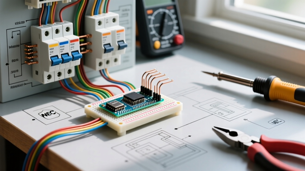
When it comes to residential and light commercial electrical systems, understanding electrical wiring diagrams for breaker panels is the foundational skill that separates certified professionals from dangerous amateurs. A panel schematic is not merely a map of where wires go; it is a logical representation of current flow, fault protection, and grounding architecture. In 2026, with the widespread adoption of the NEC 2023 and localized 2026 amendments, these diagrams also dictate the placement of Arc Fault Circuit Interrupters (AFCIs) and Ground Fault Circuit Interrupters (GFCIs) at the breaker level rather than the receptacle level.
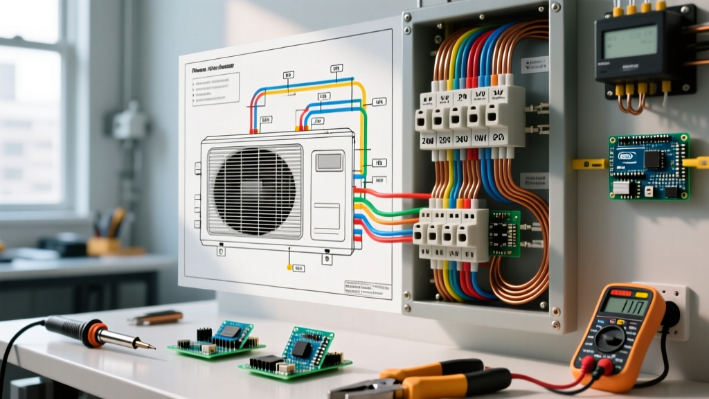
A standard main service panel diagram revolves around three critical nodes: the service entrance conductors, the main disconnecting means, and the branch circuit distribution bus. Whether you are working with a legacy Square D QO load center or a modern Eaton BR series, the underlying schematic logic remains consistent. The hot legs (L1 and L2) deliver 240V across the main breaker, splitting into 120V alternating phases down the stab bus bars. The neutral bus bonds directly to the ground bus and the enclosure in a main panel, a detail that is paramount when interpreting the grounding schematic.
Decoding Standard Schematic Symbols
Before tracing lines on a blueprint, you must recognize the standardized symbols used by electrical engineers and manufacturers like Schneider Electric and Eaton. Misinterpreting a symbol can lead to catastrophic miswiring, such as confusing a double-pole breaker with two independent single-pole breakers.
| Symbol Representation | Component Name | Panel Application & Context |
|---|---|---|
| Single Switch (SPST) | Single-Pole Breaker | 120V branch circuit protection (e.g., 15A/20A lighting). |
| Ganged Switches (DPST) | Double-Pole Breaker | 240V appliance protection (e.g., 30A for dryers, 50A for ranges). |
| Parallel Lines with Hash | Bus Bar (Hot) | The alternating copper stabs that distribute power to breakers. |
| Line to Earth (Ground) | Grounding Electrode Conductor | Connects the panel ground bus to the physical earth (ground rods/UFER). |
| Circle with 'CT' | Current Transformer | Used in smart panels (e.g., SPAN, Leviton) for branch-level monitoring. |
Step-by-Step: Reading a Main Service Panel Schematic
To effectively troubleshoot or install a panel, you must read the diagram sequentially from the utility drop to the furthest branch circuit.
- Trace the Service Entrance: Identify the service conductors on the diagram. For a standard 200A residential service, the schematic will specify 2/0 AWG copper or 4/0 AWG aluminum. These lines terminate at the main lugs or the main breaker.
- Identify the Main Disconnect: Locate the main breaker symbol (usually a large DPST switch rated for 200A). According to NFPA NEC Article 230, this must be capable of disconnecting all ungrounded conductors simultaneously.
- Map the Bus Bar Phasing: Follow the L1 and L2 lines from the main breaker to the bus bars. Notice how the schematic shows alternating connections. This is critical for multi-wire branch circuits (MWBCs), which must connect to different phases to prevent overloading the shared neutral.
- Verify Neutral and Ground Bonding: In a main panel diagram, you will see a specific symbol or jumper line connecting the neutral bus bar to the ground bus bar and the metal enclosure. This is the "main bonding jumper."
Critical Edge Cases: Subpanels vs. Main Panels
The most common fatal error made by DIYers interpreting panel diagrams is failing to distinguish between a main service panel and a subpanel. The wiring diagrams for these two setups differ in one critical, life-saving way: the neutral-to-ground bond.
Expert Warning: In a subpanel schematic, the neutral bus bar must be isolated from the ground bus bar and the metal enclosure. If you apply a main panel diagram's bonding logic to a subpanel, return neutral current will travel back to the main panel via the bare copper ground wire, energizing the grounding system and creating a severe shock hazard.
When reading a subpanel diagram, look for the explicit removal of the green bonding screw or strap. Furthermore, the schematic will dictate a 4-wire feed (two hots, one neutral, one ground) from the main panel, as mandated by NEC Article 250. Older 3-wire subpanel diagrams are obsolete and violate current 2026 safety codes.
Real-World Torque and Wire Gauge Specifications
Modern electrical diagrams and manufacturer installation sheets no longer leave terminations to "hand-tight" guesswork. NEC 110.14(D) strictly requires the use of calibrated torque tools for connections. When reviewing the wiring diagram and accompanying spec sheet for a breaker like the Square D QO2100CP (100A Main), you must cross-reference the torque table.
| Wire Gauge (AWG/kcmil) | Conductor Material | Typical Lug Torque Spec (in-lbs) | Common Application |
|---|---|---|---|
| #14 - #10 | Copper | 35 - 40 in-lbs | 15A - 30A Branch Breakers |
| #8 - #4 | Copper / Aluminum | 45 - 60 in-lbs | 40A - 100A Feeder / Subpanel |
| #2 - #1/0 | Copper | 150 - 250 in-lbs | 100A - 150A Main Service Lugs |
| 2/0 - 4/0 | Aluminum | 250 - 350 in-lbs | 200A Main Service Lugs |
Note: Always defer to the specific torque values printed on the panel label or manufacturer datasheet, as alloy compositions and lug designs vary between brands like Eaton, Siemens, and Square D.
Common Wiring Diagram Mistakes and Failure Modes
Even when understanding electrical wiring diagrams theoretically, field execution often reveals edge cases. Be aware of these common failure modes:
- Double-Tapping Breakers: Many diagrams show one wire per lug. However, specific breakers, such as the Square D QO series (15A-30A), feature a plate-style lug designed to accept two conductors. Eaton BR breakers generally do not allow this unless explicitly marked. Double-tapping a breaker not rated for it causes poor contact, arcing, and eventual thermal failure of the bus stab.
- MWBC Handle Ties: If your diagram shows a Multi-Wire Branch Circuit (two hot wires sharing one neutral), the schematic will indicate a handle tie or a factory-ganged double-pole breaker. Failing to use a handle tie means a maintenance worker could turn off one phase, assume the neutral is dead, and receive a 120V shock from the return current of the active phase.
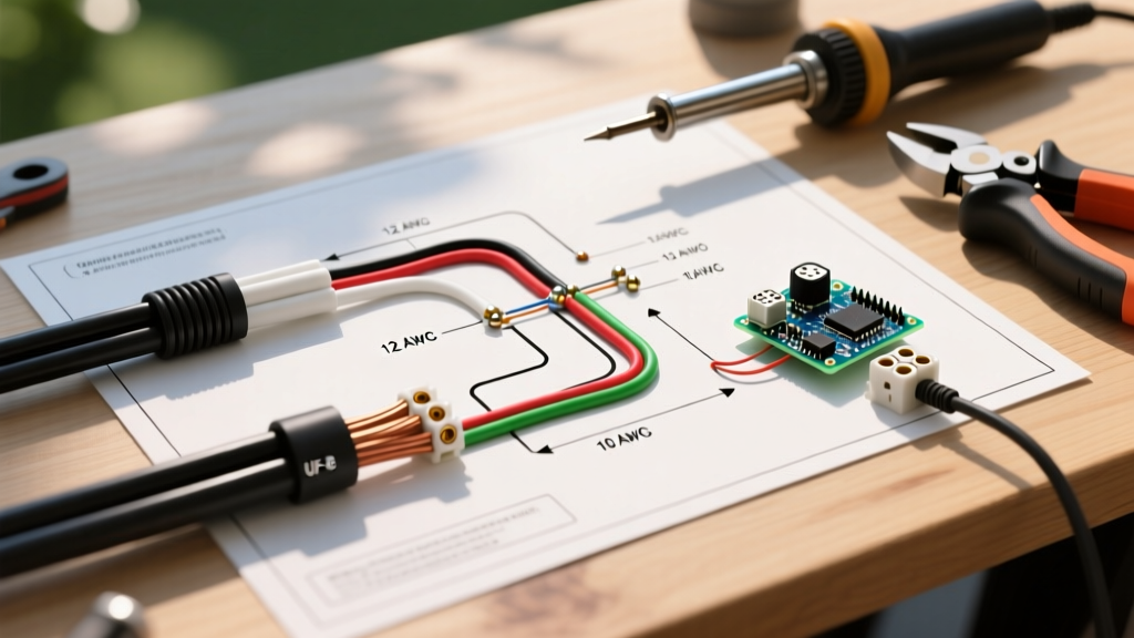
- Pigtail Overcrowding: Wire nut pigtails inside the panel can obstruct the wiring gutters. NEC 312.8 limits the fill capacity of panel wireways to 40% at any cross-section. Diagrams rarely show the physical bulk of 12 AWG THHN pigtails, leading to cramped, heat-trapping installations.
Integration with Modern Smart Panels (2026 Standards)
As of 2026, the traditional thermal-magnetic breaker schematic is being augmented by digital monitoring. Smart load centers, such as the Leviton Load Center or SPAN Panel, utilize internal Current Transformers (CTs) and digital communication buses (like CAN bus or proprietary RF) to monitor energy usage at the circuit level.
When reading a smart panel wiring diagram, you will notice the absence of traditional physical trip curves on the schematic, replaced instead by digital trip settings configurable via software. Furthermore, these diagrams heavily emphasize the placement of the neutral CT and the requirement for a dedicated, uninterrupted Wi-Fi or Ethernet backhaul for grid-interactive features (like solar curtailment or battery backup shedding). Understanding these digital schematics requires a hybrid knowledge of traditional NEC grounding rules and modern low-voltage data networking, a skill set that is rapidly becoming mandatory for advanced electrical contractors. For more on electrical safety standards regarding modern installations, refer to the OSHA Electrical Safety guidelines and Schneider Electric technical support resources.