
The Core Question: What Is a Desoldering Pump?
If you are stepping into the world of PCB rework or through-hole component salvage, you will quickly ask: what is a desoldering pump? Often referred to as a 'solder sucker,' a desoldering pump is a specialized vacuum tool designed to remove molten solder from electronic joints. By creating a sudden, high-velocity vacuum, it pulls liquid solder away from plated through-holes (PTH) and surface mount pads, allowing you to extract components without applying destructive mechanical force.
While the concept is simple, the execution requires a deep understanding of thermal dynamics, material science, and safety protocols. Improper use of a desoldering pump is one of the leading causes of lifted pads, delaminated FR-4 fiberglass, and damaged silicon dies inside sensitive ICs.
Anatomy of a Manual Solder Sucker
To understand how to use the tool safely, you must understand its internal mechanics. A high-quality manual desoldering pump (such as the industry-standard Edsyn DS017 or Engineer SS-36) consists of five critical components:
- PTFE (Teflon) Nozzle: Designed to withstand temperatures up to 260°C (500°F) without melting or sticking to the solder joint.
- Heating Chamber / Barrel: Typically made of aluminum or high-temp polycarbonate, this houses the molten solder after extraction.
- Piston and Spring Assembly: The heavy-duty spring provides the kinetic energy required to generate the vacuum spike.
- Release Catch: A mechanical trigger that holds the piston back until the user is ready to fire.
- Silicone O-Ring: Maintains the airtight seal necessary for maximum vacuum pressure.
Manual vs. Electric Desoldering Pumps: A Safety Comparison
When deciding between a manual spring-loaded pump and an electric vacuum desoldering station (like the Hakko FR-301), safety and thermal management are paramount. Below is a comparison of their operational profiles:
| Feature | Manual Spring-Loaded Pump | Electric Vacuum Pump |
|---|---|---|
| Heat Source | External (Requires separate soldering iron) | Internal (Integrated ceramic heating element) |
| Thermal Shock Risk | Moderate (User controls iron dwell time) | High (Continuous heat can overcook pads) |
| ESD Safety | High (Non-conductive housing options) | Variable (Requires grounded tip verification) |
| Solder Splatter Risk | High (Sudden mechanical release) | Low (Continuous, gentle vacuum draw) |
| Ergonomics | Poor (Requires two hands or awkward bracing) | Excellent (One-handed operation) |
Critical Safety Hazards When Using Desoldering Pumps
Desoldering is inherently more hazardous than standard soldering. You are not just melting metal; you are violently displacing it. Understanding these hazards is critical for maintaining a safe workspace.
1. Molten Solder Splatter and Ballistic Droplets
When the piston of a manual pump is released, the sudden rush of air can atomize molten solder. If the joint is overheated, or if moisture is trapped inside the through-hole, the rapid expansion of steam can cause micro-explosions. Droplets of lead-free SAC305 solder (melting point 217°C) can easily eject from the joint, posing a severe burn risk to unprotected skin and eyes. Always wear ANSI Z87.1-rated safety glasses when desoldering.
2. Toxic Flux Fume Inhalation
Reheating old solder joints vaporizes residual flux. Most electronics use rosin-based (colophony) fluxes. According to the UK Health and Safety Executive (HSE), rosin flux fumes are a known respiratory sensitizer and a leading cause of occupational asthma in electronics manufacturing. Never position your face directly above the desoldering zone. Always use a localized fume extractor with an activated carbon and HEPA filtration system.
3. Thermal Shock and Pad Delamination
The copper cladding on FR-4 PCBs is bonded with epoxy resin. If a desoldering iron is held on a pad for more than 5 to 7 seconds, the localized temperature can exceed the glass transition temperature (Tg) of the board, causing the copper pad to separate from the fiberglass substrate. Once a pad lifts, the PCB trace is often permanently destroyed.
Step-by-Step Best Practices for Damage-Free Desoldering
Follow this optimized workflow to maximize solder extraction while minimizing thermal stress on the component and the board. For deeper insights on tip selection and thermal transfer, refer to the Hakko Technical Tips database.
Phase 1: Preparation and Pre-Tinning
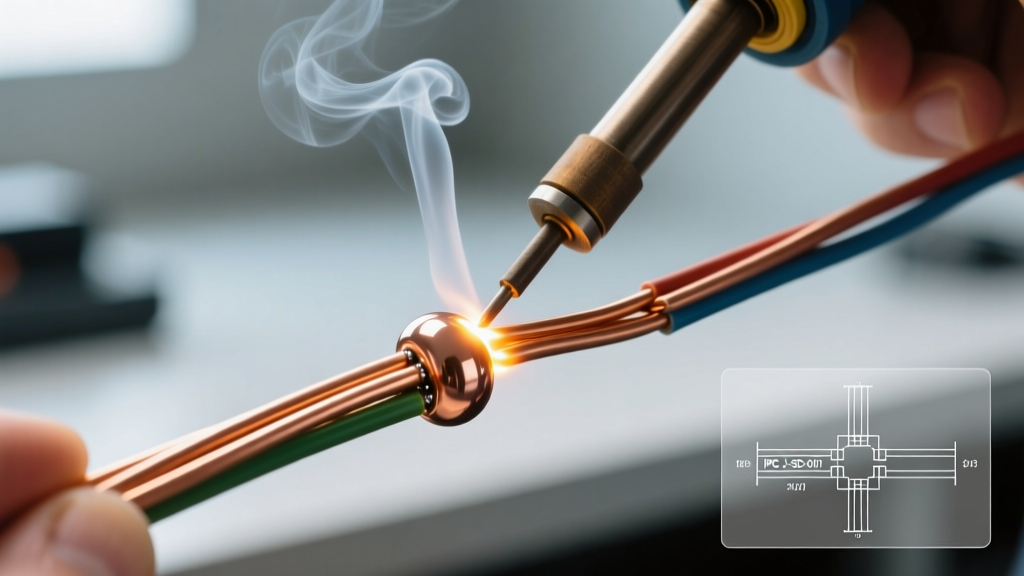
Counter-intuitively, the first step to removing old solder is adding new solder. Old solder joints are often oxidized and depleted of flux, making them poor thermal conductors. Apply a small amount of fresh, flux-cored solder to the joint. This lowers the overall melting point of the joint and creates a liquid thermal bridge between your iron tip and the existing solder.
Phase 2: Thermal Transfer
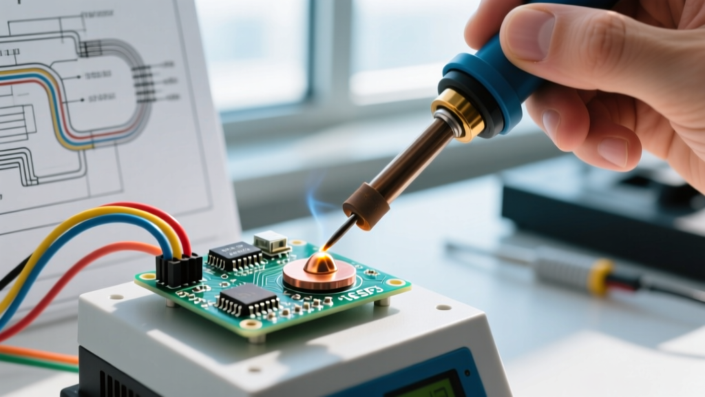
Set your soldering station to 350°C - 380°C (662°F - 716°F). While this seems high, desoldering requires rapid heat transfer to overcome the thermal mass of the component leads and the internal copper ground planes. Use a wide chisel tip or a bevel tip to maximize surface contact. Apply the iron to the joint and wait for the solder to flow into a shiny, liquid dome (usually 1.5 to 3 seconds).
Phase 3: The Vacuum Extraction
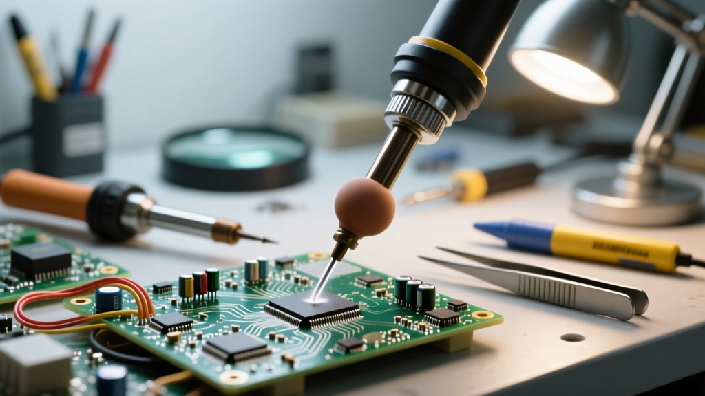
While maintaining the iron on the joint, bring the PTFE nozzle of the desoldering pump directly into the molten solder pool. Angle the pump at roughly 45 degrees to allow gravity to assist the vacuum. Trigger the pump. Crucial Safety Note: Do not remove the iron until a fraction of a second after the pump fires. Removing the iron too early results in a cold extraction, leaving behind a porous, jagged solder spike that can short adjacent traces.
Phase 4: Joint Inspection
After extraction, inspect the through-hole. A successful desoldering job will reveal a clean, shiny ring of solder around the pad with the hole completely clear. If the hole is blocked, do not blindly re-heat and pump. Instead, use a stainless steel through-hole cleaning needle to mechanically clear the barrel before applying heat again.
Pro-Tip from the Rework Bench: 'If a multi-layer board has internal ground planes, a standard desoldering pump often fails to clear the hole because the inner layers act as massive heat sinks. In these cases, pre-heat the entire PCB on a hotplate to 100°C before using the pump to reduce the thermal delta.' - Senior PCB Rework Technician
Maintenance and Nozzle Care for Longevity
A desoldering pump is only as effective as its airtight seal. Over time, flux residue and microscopic solder spheres will degrade the tool's performance.
- Daily: Wipe the PTFE nozzle with a brass wire brush while it is still warm to prevent solder buildup. Never use a steel file, as scratching the PTFE will cause molten solder to permanently fuse to the tip.
- Monthly: Unscrew the aluminum barrel and eject the collected solder slug. Inspect the silicone O-ring on the piston. If it appears flattened, cracked, or brittle, replace it immediately. A worn O-ring reduces vacuum pressure by up to 40%.
- Annually: Apply a micro-thin layer of high-temperature silicone grease to the piston shaft to maintain smooth operation and preserve the seal.
When to Abandon the Pump: Alternative Desoldering Methods
While understanding what a desoldering pump is and how to use it is essential, it is not a universal solution. You must recognize when the pump is the wrong tool for the job to prevent catastrophic board damage.
- Surface Mount Devices (SMDs): Never use a desoldering pump on SMD pads. The mechanical force of the nozzle will rip the microscopic pads off the board. Use desoldering braid (copper wick) instead.
- High-Density BGAs and QFNs: Components with hidden thermal pads or hundreds of fine-pitch leads require a hot air rework station or an infrared (IR) reflow oven to heat all joints simultaneously.
- Extremely Fragile Traces: If you are working on vintage electronics or flexible printed circuits (FPC), the mechanical shockwave of a manual pump can shatter brittle copper traces. Opt for a low-vacuum electric desoldering station or chemical desoldering gels.
Conclusion
Mastering the desoldering pump is a rite of passage for any serious electronics hobbyist or professional technician. By respecting the thermal limits of your materials, utilizing proper PPE, and adhering to the pre-tinning and extraction best practices outlined above, you can salvage expensive components and repair complex PCBs safely. For further reading on laboratory and workspace safety protocols, consult the MIT Environment, Health & Safety (EHS) soldering guidelines. Always prioritize a clean, well-ventilated workspace and let the heat—and the vacuum—do the heavy lifting.