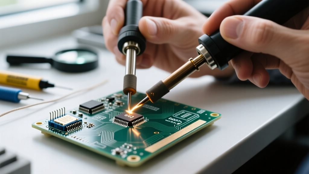

The Hidden Cost of Incorrect Soldering Temperatures
When a solder joint fails, most hobbyists and even some technicians immediately blame the flux chemistry or the solder wire quality. However, according to industry failure analysis, over 80% of manual soldering defects stem directly from improper thermal management. Troubleshooting soldering temperatures is not merely about setting a dial to a specific number; it requires a deep understanding of thermal mass, tip geometry, alloy phase transitions, and the specific heat capacity of your printed circuit board (PCB).
Whether you are using a budget-friendly Pinecil V2 ($26) or a professional Hakko FX-951 ($250), setting the wrong temperature will result in cold solder joints, lifted copper pads, or charred flux residue. This comprehensive troubleshooting guide will help you diagnose thermal faults, calibrate your equipment, and apply the exact heat profiles required for flawless PCB assembly.
Diagnostic Matrix: Identifying Temperature-Related Defects
Before adjusting your station, you must accurately diagnose the visual symptoms of the failed joint. Use the following matrix to pinpoint the root thermal cause.
| Symptom | Visual Cue | Root Temperature Cause | Immediate Fix |
|---|---|---|---|
| Cold Solder Joint | Dull, grainy, bulbous appearance; poor wetting | Tip temp too low OR thermal mass mismatch | Increase temp by 15°C or switch to a wider bevel/chisel tip. |
| Lifted Copper Pad | Pad separates from FR4 substrate; trace tearing | Temp too high (>380°C) + dwell time >3 seconds | Drop to 320°C, apply active liquid flux, and use board pre-heating. |
| Charred Flux | Black, crusty residue; solder refuses to flow | Tip temp exceeding flux activation burn-off point | Lower temp by 20°C; switch to No-Clean or RA flux with higher thermal tolerance. |
| Tombstoning (SMD) | One end of a surface-mount component lifts vertically | Uneven pad heating creating a severe temperature gradient | Use a wider chisel tip to bridge both pads simultaneously, or introduce 280°C hot air. |
| Component Heat Damage | Melted connector housings, scorched IC packages | Excessive thermal transfer via prolonged dwell time | Use a micro-pencil tip for precision, apply Kapton tape heat shields, and limit contact to 1.5s. |
The Alloy Baseline: Know Your Melting Points
You cannot troubleshoot soldering temperatures without first establishing the baseline melting point of your specific solder alloy. Applying a universal temperature across different chemistries is a primary cause of joint failure.
- Sn63/Pb37 (Eutectic Leaded): Melts at exactly 183°C (361°F). Because it transitions instantly from solid to liquid without a plastic state, it is forgiving. Ideal iron setting: 300°C to 330°C.
- SAC305 (Lead-Free): Melts at 217°C (423°F). This alloy requires significantly more thermal energy to achieve proper wetting and is prone to creating grainy joints if under-heated. Ideal iron setting: 340°C to 360°C.
- Sn42/Bi57 (Low-Temperature): Melts at 138°C (280°F). Often used for step-soldering or repairing heat-sensitive components. Ideal iron setting: 220°C to 250°C. Warning: Never mix this with lead-free alloys, or you will create a brittle, low-melting-point eutectic that fails under mechanical stress.
For authoritative data on alloy compositions and their specific wetting behaviors, always refer to the Kester Alloy Datasheets, which provide exact liquidus and solidus temperatures for industrial applications.
Troubleshooting Thermal Mass Mismatches
A common scenario in troubleshooting soldering temperatures involves attempting to solder a standard through-hole capacitor to a heavy 2oz copper ground plane. The iron reads 350°C, but the solder refuses to melt. Why?
The issue is not the temperature setting; it is the thermal recovery rate and tip geometry. A massive ground plane acts as a giant heat sink, pulling thermal energy away from the joint faster than a standard micro-pencil tip can replenish it.
The Fix: Geometry and Wattage
- Change the Tip Geometry: Swap your conical or micro-pencil tip (e.g., Weller RT3) for a heavy-duty chisel or bevel tip (e.g., Hakko D24 or Weller XDS series). The increased surface area maximizes thermal transfer efficiency.
- Verify Wattage: Temperature is the target, but wattage dictates recovery speed. A 45W iron will stall on a ground plane. Upgrade to a 70W+ station like the Weller WE1010NA ($125) or the Hakko FX-951 ($250) to ensure the heating element can push continuous current to the tip.
- Introduce Bottom Pre-Heating: For multi-layer boards with internal copper pours, use a PTC heating mat (like the Quick 853A, ~$150) to bring the ambient PCB temperature up to 100°C. This reduces the delta-T required from your soldering iron, preventing thermal shock to the board and components.
Calibration: Verifying True Tip Temperature
The digital readout on your soldering station is a target, not a guarantee. Over time, oxidation builds up on the iron plating, creating a microscopic thermal barrier. Your station might read 350°C, while the actual working surface of the tip is only 280°C.
To properly troubleshoot, you must verify the physical temperature at the tip surface.
Pro Tip: Use a dedicated thermocouple tester like the Hakko FG-100B (~$130). Apply a small dab of high-temperature thermal paste to the sensor pad, and gently roll the tinned tip across the sensor. This ensures an accurate thermal bridge. If the measured temperature deviates by more than 5°C from your station's display, use the station's internal calibration offset menu to correct the variance.
Routine calibration is heavily emphasized in professional manufacturing environments. As outlined in the IPC J-STD-001 Standard for soldered electrical assemblies, maintaining strict thermal profiling and equipment calibration is mandatory for Class 2 and Class 3 high-reliability electronics.
Edge Case: Aluminum Core PCBs (MCPCBs)
Soldering high-power LEDs to Metal Core Printed Circuit Boards (MCPCBs) presents a unique thermal challenge. The dielectric layer between the copper trace and the aluminum base is a thermal insulator, yet the aluminum base acts as a massive heat sink.
- The Failure Mode: Applying too much heat for too long will delaminate the dielectric layer, ruining the board's thermal conductivity and electrical isolation.
- The Protocol: Set a high-wattage iron to 380°C using a wide bevel tip. Apply aggressive RA (Rosin Activated) flux. The goal is to transfer maximum heat in the absolute minimum time. Your dwell time must not exceed 1.5 to 2.0 seconds per pad. If the solder does not flow within 2 seconds, remove the iron, let the board cool, add more flux, and try again with a pre-heater.
Summary: Best Practices for Thermal Management
Mastering soldering temperatures requires moving beyond arbitrary dial settings and adopting a physics-based approach to heat transfer. Always match your temperature to the specific alloy's liquidus point, adjust your tip geometry to match the pad's thermal mass, and verify your equipment with a physical thermocouple tester. By systematically troubleshooting these variables, you will eliminate cold joints, protect sensitive components, and achieve professional-grade, shiny, and reliable solder fillets every time. For further foundational techniques on heat application and flux management, the SparkFun Soldering Guide remains an excellent visual resource for both beginners and seasoned engineers.