
When a fabricated assembly fails in the field, the root cause almost always traces back to the thermal joining process. Understanding the metallurgical boundaries between soldering, welding, and brazing is the first step in diagnosing why a joint fractured, leaked, or lost electrical continuity. While all three processes utilize heat and filler metals, their operating temperatures, capillary mechanics, and base-metal interactions are vastly different.
In this comprehensive troubleshooting guide, we break down the specific failure modes of each technique and provide actionable, step-by-step rework protocols to restore joint integrity.
The Metallurgy of Failure: Diagnostic Matrix
Before applying a fix, you must correctly identify the process used. Misapplying a soldering fix to a brazed joint will result in catastrophic thermal failure. The The Welding Institute (TWI) defines these processes primarily by temperature and base-metal melting. Below is a quick diagnostic matrix to identify your joint type and its primary vulnerability.
| Process | Temp Range | Base Metal State | Common Filler Alloys | Primary Failure Mode |
|---|---|---|---|---|
| Soldering | < 840°F (450°C) | Solid (No melting) | SAC305, Sn63/Pb37 | Cold joints, dewetting, intermetallic overgrowth |
| Brazing | > 840°F (450°C) | Solid (No melting) | BCuP-5, BAg-24, Brass | Flux inclusions, capillary starvation, erosion |
| Welding | > 2500°F (1370°C) | Liquid (Melted) | ER70S-6, ER4043 | Porosity, undercut, lack of fusion, cracking |
Troubleshooting Soldering Defects (Electronics & Wiring)
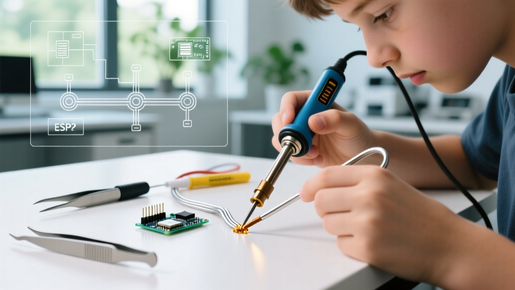
Modern electronics and heavy-gauge wiring rely heavily on lead-free alloys like SAC305 (Sn96.5/Ag3.0/Cu0.5). While environmentally compliant, SAC305 requires higher tip temperatures (typically 350°C - 380°C) and exhibits a narrower plastic phase than legacy tin-lead, making it highly susceptible to specific defects.
1. Cold Solder Joints and Dewetting
A cold joint occurs when the solder melts, but the base metal (pad or wire) fails to reach the alloy's liquidus temperature. The result is a dull, grainy, or convex joint with poor electrical continuity.
- The Cause: Insufficient thermal mass transfer. Using a micro-pencil tip on a 10 AWG ground wire will fail because the tip cannot recover heat fast enough.
- The Fix: Switch to a chisel or bevel tip (e.g., Hakko T18-D24 or Weller RT4) to maximize surface contact. Apply a generous amount of flux (ROL0 or ROL1 classification) before applying heat. Heat the wire and pad simultaneously for 3-5 seconds before feeding the solder.
2. Intermetallic Compound (IMC) Overgrowth
If a soldering iron is left on a joint for too long (exceeding 8-10 seconds), the copper-tin intermetallic layer grows excessively thick. This layer is highly brittle and will fracture under minor mechanical vibration.
- The Fix: Desolder the joint completely using a high-capacity desoldering pump (like the Engineer SS-02) or copper braid. Clean the pad with 99% isopropyl alcohol, re-tin with fresh flux-cored wire, and reflow in under 4 seconds.
Brazing Failures: HVAC, Plumbing, and Structural
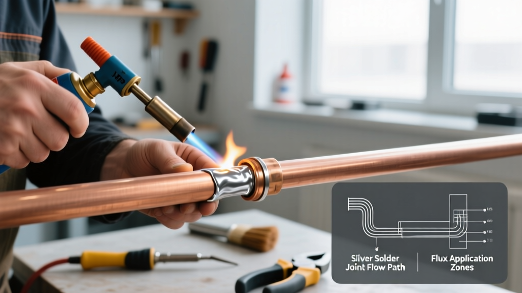
Brazing relies on capillary action to draw molten filler metal into the joint gap (ideally 0.002 to 0.005 inches). According to the American Welding Society (AWS), improper gap clearance and thermal management are the leading causes of brazed joint failure.
Capillary Starvation and Void Formation
When brazing copper-to-copper refrigeration lines using a BCuP-5 (15% silver, copper-phosphorus) alloy, you may notice the filler metal pooling on the outside rather than drawing inside the joint.
- The Cause: The joint gap is too wide (exceeding 0.008 inches), or the base metal was not heated uniformly, causing the filler to freeze before completing its capillary travel.
- The Fix: You cannot simply 'melt more' brazing alloy into a starved joint. You must cut the fitting out, re-deburr the tubing to ensure a tight slip-fit, and re-braze. Always apply heat to the base metal away from the joint line, allowing the heat to conduct inward and pull the alloy via capillary action.
Base Metal Erosion (Notching)
Erosion occurs when the base metal dissolves into the molten filler alloy, creating a physical notch at the edge of the joint. This is a severe stress riser.
- The Cause: Overheating the joint or using a filler metal with a liquidus temperature too close to the base metal's melting point. This is common when brazing thin-walled copper with high-silver BAg alloys using an oxy-acetylene torch set to an oxidizing flame.
- The Fix: Switch to a neutral or slightly carburizing flame. Use an induction brazing system or an air-acetylene torch (like the Bernzomatic TS8000) for better thermal control on thin materials, keeping the temperature strictly below 1,400°F.
Expert Insight: Never use a BCuP (copper-phosphorus) alloy to braze copper to brass or steel. The phosphorus reacts with the iron or zinc to form brittle phosphides at the interface, leading to immediate joint failure under vibration. Always use a BAg (silver) alloy with a separate white flux paste for dissimilar metals.
Welding Defects: TIG and MIG Troubleshooting
Welding involves the coalescence of base metals, creating a heat-affected zone (HAZ) that is highly susceptible to metallurgical changes. Troubleshooting welds requires understanding shielding gas dynamics and electrical parameters.
Porosity in MIG (GMAW) Welds
Porosity presents as wormholes or spherical gas pockets trapped inside the weld bead, severely compromising tensile strength.
- The Cause: Loss of shielding gas coverage. This can be due to drafts in the shop, excessive wire stick-out (over 3/4 inch), or hydrocarbons (oil/rust) on the base metal vaporizing into the weld pool.
- The Fix: Grind out the porous section using an angle grinder with a 24-grit flap disc until clean, solid base metal is exposed. Clean the area with an acetone wipe. Verify your 75% Argon / 25% CO2 gas flow is set to 20-25 CFH, and maintain a strict 1/2-inch wire stick-out during the re-weld.
TIG (GTAW) Tungsten Inclusions and Undercut
Undercut is a groove melted into the base metal adjacent to the weld toe, left unfilled by weld metal. Tungsten inclusions occur when the non-consumable electrode touches the weld puddle.
- The Cause (Undercut): Amperage is too high, or travel speed is too fast, causing the arc to gouge the edges without leaving enough filler to fill the crater.
- The Cause (Inclusions): Dipping the tungsten too deep into the puddle or using an incorrect shielding gas flow rate.
- The Fix: For undercut, lower the amperage by 10-15% and add a slight 'whip and pause' motion to allow the puddle to wet the toes. For tungsten inclusions, you must stop, break off the contaminated tungsten tip, re-grind it longitudinally on a diamond wheel, and grind out the contaminated weld metal before restarting. The IPC-A-610 standard strictly forbids inclusions in high-reliability electrical welds and solder terminations.
Step-by-Step Universal Rework Protocol
Regardless of whether you are fixing a soldered PCB trace, a brazed HVAC line, or a welded steel chassis, follow this strict rework sequence to ensure joint integrity:
- Isolate and Depressurize: Ensure electrical circuits are discharged and fluid lines are evacuated to 0 PSI. Heat applied to trapped gases or moisture will cause explosive outgassing and severe porosity.
- Mechanical Removal: Do not attempt to 'melt over' a bad joint. Use desoldering braid for electronics, a hacksaw for brazed pipes, or an angle grinder for welds to remove the defective filler entirely.
- Chemical/Mechanical Cleaning: Remove all oxidation and old flux. Use stainless steel wire brushes for aluminum/brass, and 120-grit sanding for steel. Wipe with 99% IPA or acetone.
- Flux Application (If applicable): Apply fresh, process-appropriate flux. Never reuse activated, burnt flux residue.
- Controlled Thermal Application: Re-apply heat using the correct profile. Monitor the filler metal's flow; it should be drawn by capillary action or surface tension, not forced by the heat source.
- Post-Clean and Inspect: Remove all corrosive flux residues (especially water-soluble and borax-based brazing fluxes) using hot distilled water and a stiff brush. Inspect visually under 10x magnification for micro-cracks.
Frequently Asked Questions (FAQ)
Can I braze over a previously soldered joint?
No. The extreme heat required for brazing (typically 1,200°F+) will instantly vaporize the tin and lead in a soldered joint, causing severe porosity and toxic fume release. You must mechanically remove all solder and clean the base metal with a wire brush before attempting to braze.
Why does my silver solder (brazing alloy) ball up instead of flowing?
Silver solder (like BAg-24) requires a specific activation temperature from the base metal to flow. If it balls up, your base metal is too cold, or the joint is heavily oxidized. Ensure you are using a high-temperature white brazing flux and heating the base metal, not the filler rod directly with the torch flame.
How do I fix a micro-crack in a TIG weld on aluminum?
Aluminum weld cracks (usually centerline crater cracks) occur due to improper crater fill or high silicon content mismatch. To fix it, use a grinder to completely V-groove the crack out. Preheat the aluminum to 200°F to reduce thermal shock, and re-weld using a 4043 or 5356 filler rod, ensuring you use a crater-fill function on your TIG inverter to taper off the amperage at the end of the pass.