
The Metallurgy of a Perfect Wire Splice
Amateurs treat solder as an electrical glue; professionals understand it as a complex metallurgical bond. When soldering wires together for aerospace, automotive, or high-reliability industrial applications, the goal is to create a continuous intermetallic compound (IMC) layer between the copper conductor and the tin-based alloy. This IMC layer—primarily composed of Cu6Sn5 and Cu3Sn—should ideally measure between 1 and 3 microns in thickness. If the heat dwell time is too short, the IMC fails to form, resulting in a high-resistance cold joint. If the dwell time is too long, the IMC layer grows excessively thick, becoming brittle and prone to mechanical fracture under vibration.
According to the NASA Electronic Parts and Packaging (NEPP) Program, wire-to-wire soldering requires strict adherence to thermal profiles to prevent insulation meltdown while ensuring complete capillary wetting. This guide outlines the professional methodology for executing flawless wire splices, aligned with modern IPC J-STD-001 requirements.
2026 Professional Tooling & Material Matrix
Achieving repeatable, IPC-compliant results requires active temperature-controlled stations and precision alloys. The era of using generic 60/40 plumbing solder for electronics is over. Below is the recommended professional loadout for wire splicing.
| Category | Professional Choice | Approx. Cost (2026) | Technical Justification |
|---|---|---|---|
| Soldering Station | Hakko FX-951 or Weller WE1010NA | $135 - $265 | Active tip sensing with < 10°C thermal recovery. Essential for high-AWG wires that act as massive heat sinks. |
| Wire Solder | Kester 245 Sn63/Pb37 (0.031") | $40 / lb | Eutectic alloy (melts at 183°C) with No-Clean (NC) flux core. 0.031" diameter prevents over-application on 18-24 AWG wires. |
| Lead-Free Alt. | Indium SAC305 (0.020") | $95 / lb | Required for RoHS-compliant commercial builds. Melts at 217°C; requires higher iron temps (350°C-380°C). |
| External Flux | Kester 951 No-Clean Liquid | $25 / gal | Used sparingly to re-wet oxidized vintage wires or heavy-gauge battery cables where core flux is insufficient. |
| Insulation | 3M EPS300 Dual-Wall Heat Shrink | $45 / spool | 3:1 shrink ratio with thermoplastic adhesive liner. Melts at 120°C to form a waterproof, strain-relieved environmental seal. |
Pro-Tip on Tip Geometry: When soldering wires together, avoid standard conical (B-type) tips. They offer poor surface area contact. Use a chisel (D-type) or a hoof/bevel (C-type) tip sized to match the combined diameter of your wire splice to maximize thermal transfer.
Executing the Lineman's Splice: Step-by-Step
While solder provides electrical conductivity, it lacks tensile strength. A professional wire splice must be mechanically secure before the iron ever touches the copper. The Lineman's splice (or Western Union splice) remains the gold standard for joining two solid or stranded wires.
- Precision Stripping: Strip exactly 1.5 inches of insulation from both wire ends. Use thermal wire strippers (like the Hakko CHP) or calibrated mechanical strippers to ensure zero copper strand nicking. A single nicked strand reduces the wire's tensile strength by up to 40%.
- Pre-Slide Insulation: Slide a 2-inch piece of 3M EPS300 heat shrink tubing onto one of the wires before beginning the splice. Position it at least 4 inches away from the working area to prevent premature shrinking from radiant heat.
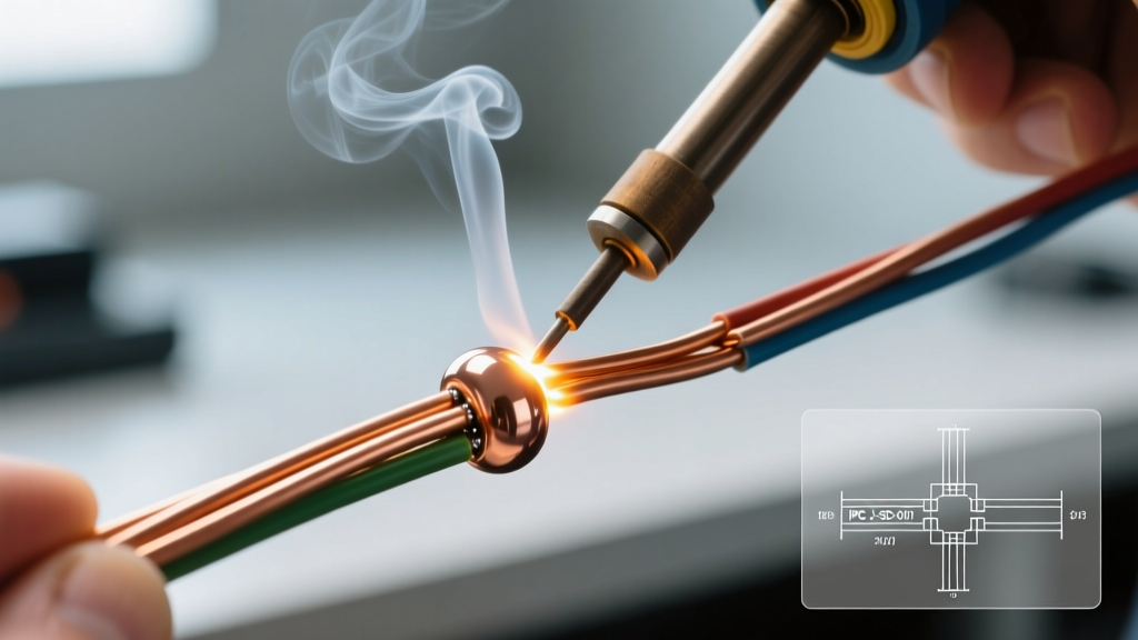
- The Cross & Twist: Cross the two stripped wires in an 'X' shape, intersecting about one-third of the way down the stripped length. Twist the longer ends around each other tightly, maintaining a 45-degree pitch angle. Aim for 3 to 4 full twists per side.
- Flux Application: Apply a micro-drop of Kester 951 flux to the twisted joint. This breaks down surface oxides and lowers the surface tension of the molten solder.
- Thermal Transfer: Place the pre-tinned chisel tip directly against the copper mass (not the solder). Count to two, then feed the Sn63/Pb37 solder into the wire joint, not the iron tip. Capillary action will draw the solder into the core of the twist.
- Cooling Phase: Remove the heat, then the solder. Hold the wires perfectly still for 3-5 seconds until the solder transitions from a shiny liquid to a dull, matte solid. Moving the joint during the plastic phase causes micro-fractures (grain boundary tearing).
IPC J-STD-001 Acceptability Criteria for Wire Joints
Quality control in professional environments relies on visual inspection criteria. The IPC J-STD-001 standard defines what constitutes a pass or fail for soldered wire connections. Use this matrix to audit your own work.
| Inspection Point | Target (Ideal) | Acceptable (Pass) | Defect (Fail) |
|---|---|---|---|
| Wetting & Fillet | Smooth, shiny, concave fillet covering the entire splice with visible wire outlines. | Dull finish (if lead-free), slightly convex, but fully wetted and covering all strands. | Non-wetted areas, spherical 'blob' shape, or exposed bare copper. |
| Solder Wicking | Solder wicks into the strands but stops before the insulation jacket. | Solder wicks under the insulation jacket but does not compromise the wire's flexibility. | Solder wicks to the bend radius or causes the insulation to bulge/stiffen, creating a stress concentration point. |
| Insulation Damage | Zero scorching, melting, or retraction of the wire jacket. | Minor discoloration of the jacket, but no structural compromise or exposed copper. | Melted insulation, burnt flux residue bridging conductors, or jacket pulled back exposing bare wire outside the joint. |
| Cleanliness | Zero visible flux residue or splatter. | Clear, non-conductive No-Clean residue remaining (if not using a cleaning protocol). | Sticky, corrosive, or conductive residue; charred flux trapping moisture. |
Advanced Insulation: Beyond Electrical Tape
Electrical tape is strictly prohibited in professional and aerospace harnesses. It degrades under UV light, unravels under thermal cycling, and traps moisture against the copper, accelerating galvanic corrosion. The professional standard is dual-wall, adhesive-lined polyolefin heat shrink.
When using 3M EPS300 or equivalent 3:1 shrink tubing, the inner thermoplastic adhesive melts at approximately 120°C, while the outer polyolefin shrinks at 90°C and fully recovers by 120°C. The technique matters: apply heat starting from the center of the tubing and move outward toward the wire jackets. This forces air and excess adhesive out the ends, creating a hermetic seal. If you heat the ends first, you trap air inside, creating a void where condensation can accumulate and cause dendritic growth over time.
Troubleshooting Edge Cases & Failure Modes
Even with premium tooling, edge cases arise. Here is how to diagnose and correct the most common professional failure modes:
- Severe Solder Wicking: Cause: Applying heat too close to the insulation, or using an iron temperature that is too low, causing prolonged dwell times. Fix: Increase station temp by 20°C to reduce contact time, and apply a 'heat sink' (like a hemostat clamp) between the splice and the insulation to absorb excess thermal energy.
- Grainy / Disturbed Joints: Cause: Mechanical movement during the solidification phase (the plastic state between liquidus and solidus temperatures). Fix: Use a third-hand tool or wire-holding jig. Never blow on the joint to cool it faster; rapid forced-air cooling can induce thermal shock and micro-cracking in the IMC layer.
- Rosin Burn / Charred Flux: Cause: Iron tip temperature exceeding 400°C, or reusing the same flux pool multiple times. Charred flux becomes mildly conductive and hygroscopic (absorbs water). Fix: Cap your iron when not in use. Clean the splice with 99% Isopropyl Alcohol and a lint-free swab if using RMA (Rosin Mildly Activated) flux, or switch to a high-quality No-Clean formulation like Kester 245.
- Strand Pop-Out (Birdcaging): Cause: The wire was improperly stripped, or the strands were splayed before twisting. Fix: Discard the joint. Cut back past the heat-affected zone, re-strip, and re-twist. Never attempt to 'solder over' a birdcaged wire joint to hold the strands down; the mechanical integrity is already compromised.
Mastering the art of soldering wires together is less about the physical act of melting metal and more about thermal management, material science, and strict adherence to inspection criteria. By upgrading your tooling, respecting the intermetallic bond, and utilizing adhesive-lined environmental seals, your wire harnesses will meet the rigorous demands of modern electronics and survive years of operational stress.