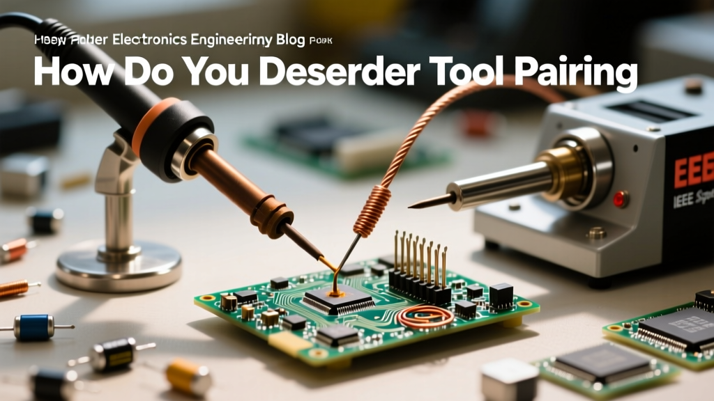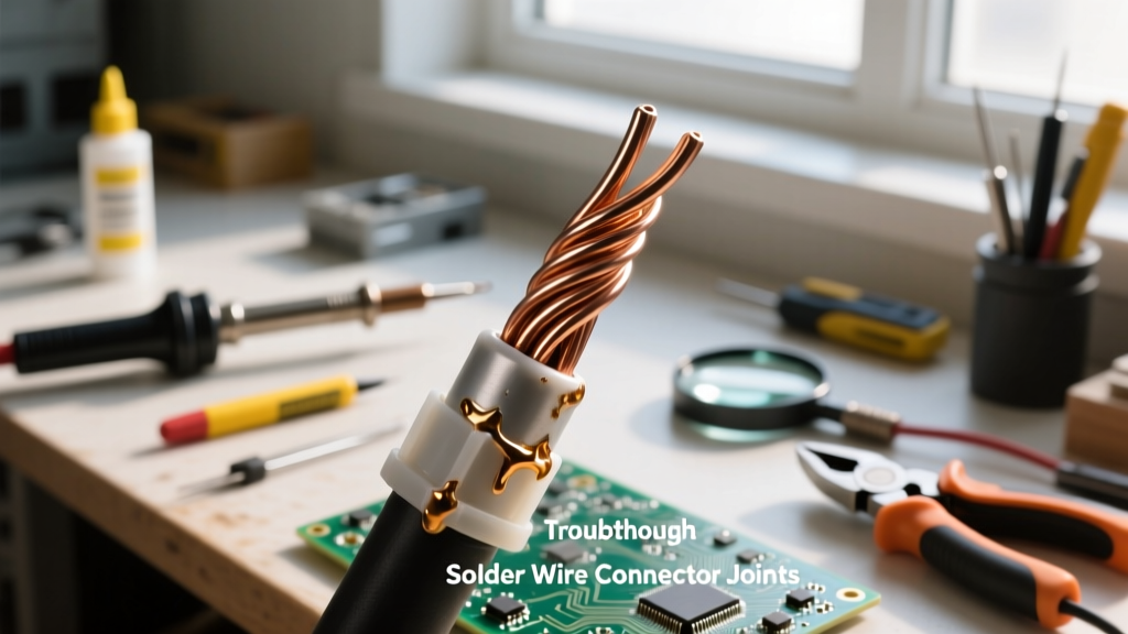

The Metallurgy of a Perfect Wire Joint
Soldering wires is often misunderstood as simply 'gluing' two pieces of metal together with heat. In reality, you are engineering a metallurgical bond. When molten solder meets clean, heated copper, a microscopic intermetallic compound (IMC) layer—specifically Cu6Sn5—forms at the boundary. This layer is what actually conducts electricity and provides mechanical strength. If the copper is oxidized, or if the thermal mass of the wire absorbs heat faster than your iron can deliver it, the IMC layer fails to form, resulting in a high-resistance, brittle cold joint.
Whether you are wiring a high-current drone ESC, repairing automotive harnesses, or building audio cables, mastering the physical technique of soldering wires ensures your connections survive thermal cycling and mechanical vibration. This guide follows the stringent criteria outlined in the NASA Workmanship Standards and the IPC-A-610 acceptability requirements for electronic assemblies.
Essential Tool Matrix for 2026
Using the wrong tool profile is the number one cause of failed wire joints. Conical iron tips, for example, have a tiny surface contact area with cylindrical wires, leading to severe thermal stalling on anything larger than 20 AWG. Below is the optimized gear loadout for professional-grade wire splicing.
| Category | Recommended Model | Specifications & Pricing (2026) | Why It Matters |
|---|---|---|---|
| Soldering Station | Weller WE1010NA | 70W, Digital Temp Control (~$115) | Fast thermal recovery prevents stalling on 12-16 AWG wires. |
| Iron Tip Profile | Weller ETA (Chisel) | 1.6mm / 0.062in Chisel (~$12) | Maximizes surface area contact for rapid heat transfer into the copper strands. |
| Wire Strippers | Klein Tools 11055 | AWG 10-20 Precision (~$28) | Prevents nicking the copper, which creates stress risers and reduces ampacity. |
| Solder Alloy | Kester 44 (63/37) | Sn/Pb Rosin Core, 0.031in (~$38/lb) | Eutectic 63/37 melts at a single temperature (183°C), preventing disturbed joints. |
| Insulation | 3M FP-301 Heat Shrink | 2:1 Shrink Ratio, Polyolefin (~$15/spool) | Provides environmental sealing and strain relief without melting under standard iron temps. |
Step 1: Precision Stripping and Mechanical Prep
The goal of stripping is to expose the bare copper without compromising the structural integrity of the individual strands. A single nick from a dull pair of strippers can cause the wire to snap under vibration later.
- Select the Correct Gauge Hole: Match your wire precisely to the stripper. For 18 AWG stranded wire, use the 18 AWG hole on the Klein 11055. Forcing a 16 AWG wire into an 18 AWG hole will shear the outer strands.
- Strip Length Calculation: The exposed length should be exactly enough to complete your mechanical splice plus a 1/16-inch buffer. For a standard Western Union splice on 18 AWG wire, strip exactly 1.25 inches (32mm) from each end.
- Inspect the Strands: If any copper strands are cut or deeply scored, cut the wire back and strip again. Do not attempt to solder compromised copper.
Step 2: The Pre-Tinning Protocol
Pre-tinning (or 'pre-stripping' in some legacy manuals) coats the individual strands in solder, fusing them into a single solid mass before the mechanical splice. This prevents stray strands from poking out of the final joint and shorting against adjacent circuits.
- Set the Temperature: Set your Weller WE1010NA to 350°C (662°F) for 63/37 leaded solder. If using lead-free SAC305, increase to 380°C (716°F).
- Flux the Tip and Wire: If your solder does not have an aggressive enough flux core, apply a tiny dab of external rosin flux (RMA) to the bare wire. This breaks down surface oxides instantly.
- Apply Heat and Solder: Place the flat of the chisel tip against the wire. Wait exactly 1 to 1.5 seconds for the copper to reach flow temperature, then feed the Kester 44 solder into the wire, not just the iron tip. Capillary action will pull the molten solder between the strands.
- Stop Before the Insulation: Critical Warning: Leave a 1/8-inch (3mm) gap of bare, untinned copper between the solder line and the wire insulation. If solder wicks under the insulation via capillary action, the wire will become rigid at the stress point and eventually snap from vibration fatigue.
Step 3: Executing the Lineman’s Splice
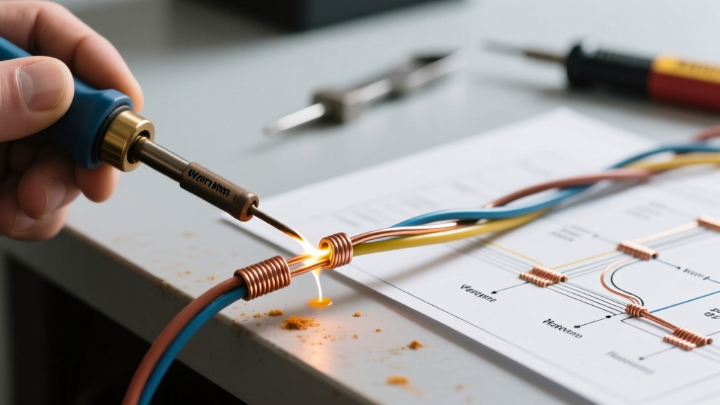
According to aerospace and automotive standards, solder should never bear mechanical load. The physical splice must hold the tensile strength. The Western Union (or Lineman's) splice is the undisputed champion for inline wire connections.
- Cross the Wires: Lay the two tinned wires across each other in an 'X' shape, about 1/3 of the way down the tinned section.
- The First Twist: Bend the right wire up and over the left wire, wrapping it tightly. You should achieve at least 3 to 4 tight, adjacent twists.
- The Second Twist: Repeat the process with the left wire, wrapping it around the right base wire in the opposite direction.
- Trim the Tails: Use flush cutters to snip the sharp, protruding ends of the twists. Leaving sharp tails will puncture your heat shrink tubing when it shrinks down.
Step 4: Heat Transfer and Solder Flow
Now that the mechanical joint is secure, it is time to flow solder through the splice to create the electrical and environmental seal.
- Position the Iron: Lay the flat blade of your chisel tip along the length of the splice. This maximizes thermal transfer across the entire joint simultaneously.
- Feed the Solder: Touch your solder wire to the opposite side of the splice from the iron. When the copper reaches 183°C, the solder will instantly melt and wick through the twisted strands toward the heat source. This proves the entire joint is at flow temperature.
- Observe the Fillet: A perfect joint will show a smooth, concave fillet where the solder meets the wire, with a bright, shiny finish (for leaded) or a slightly dull, satin finish (for lead-free). You should still be able to see the basic outline of the wire strands beneath the solder; you are not trying to encase the joint in a massive ball of solder.
- Dwell Time: Remove the solder first, then the iron. The entire heating process should take no more than 3 to 4 seconds. Prolonged heat will degrade the PVC insulation and boil the flux, leaving corrosive residues.
Pro Tip: Never blow on a freshly soldered joint to cool it down. Disturbing the solder while it transitions from a liquid to a solid state (the 'plastic range') fractures the microscopic IMC layer, resulting in a grainy, high-resistance 'disturbed joint' that will fail under load.
Step 5: Insulation and Environmental Sealing
Bare solder joints will oxidize over time and are prone to shorting. Heat shrink tubing provides both electrical isolation and mechanical strain relief.
- Sizing: Select a 3M FP-301 heat shrink tube that slides easily over the wire's insulation but has a 2:1 shrink ratio small enough to grip the solder joint tightly.
- Placement: Slide the tubing over the joint, ensuring it overlaps the original wire insulation by at least 1/4 inch on both sides.
- Shrinking: Use a dedicated hot air rework station or a precision heat gun set to 200°C. Start heating from the center of the tubing and move outward to push trapped air out the ends. If using adhesive-lined (dual-wall) heat shrink, you will see a small bead of hot melt adhesive squeeze out the ends, confirming a waterproof environmental seal.
Troubleshooting Common Wire Soldering Failures
Even experienced technicians encounter edge cases. Use this diagnostic matrix to identify and correct flawed soldering wires techniques.
| Visual Symptom | Root Cause Analysis | Corrective Action |
|---|---|---|
| Cold Joint: Dull, grainy, or lumpy appearance. Solder looks like a ball sitting on top of the wire. | Insufficient heat transfer. The copper never reached flow temperature, preventing the Cu6Sn5 IMC layer from forming. Often caused by using a conical tip or an underpowered iron. | Switch to a chisel tip. Increase station temp by 20°C. Re-flux and reheat until solder flows smoothly into the strands. |
| Solder Wicking: Solder has traveled under the wire insulation, making the wire stiff. | Over-application of solder or holding the iron too close to the strip line, allowing capillary action to pull molten metal under the jacket. | Cut off the wick-stiffened section. Re-strip, leaving a larger 1/8-inch buffer zone before tinning. |
| Burnt Flux / Black Residue: Dark, crusty carbon buildup around the joint. | Excessive dwell time (holding the iron on the joint for >5 seconds) or iron temperature set too high (>400°C for standard rosin flux). | Clean with 99% isopropyl alcohol and a brass brush. Lower iron temp to 350°C and practice faster heat-transfer techniques. |
| Icicles / Spikes: Sharp points of solder protruding from the joint. | Flux has completely boiled off before the solder was removed, breaking surface tension. Common with thin-diameter solder on large thermal mass joints. | Use a slightly thicker solder wire (e.g., 0.040in instead of 0.020in) to deliver more flux volume per unit of solder alloy. |
Final Thoughts on Wire Integrity
Mastering the art of soldering wires requires a shift in mindset from 'melting metal' to 'managing thermal dynamics.' By respecting the metallurgy of the joint, utilizing the correct tip geometry, and executing a flawless mechanical splice before applying heat, you will produce wiring harnesses that meet rigorous aerospace and automotive reliability standards. Always verify your station's tip temperature with a digital soldering thermometer periodically, as thermal drift in budget stations can silently ruin your IMC layer formation.