
The Anatomy of a Perfect Soldering Wire Connection
A reliable soldering wire connection is not merely a mechanical bond; it is a complex metallurgical event. When done correctly, the molten solder dissolves a microscopic layer of the copper wire, forming an intermetallic compound (IMC) layer—typically Cu6Sn5. This layer is the actual electrical and mechanical bridge. Amateurs focus on melting the solder; professionals focus on managing the thermal profile to optimize this IMC layer without degrading the wire's temper or the insulation's dielectric properties.
In this guide, we break down the exact parameters, tooling, and techniques required to execute a flawless soldering wire connection in modern electronics and high-current applications.
Mechanical Preparation: The Step Amateurs Skip
The most common point of failure in a soldering wire connection occurs before the iron is even plugged in. Improper stripping and wire preparation introduce micro-fractures and reduce the effective cross-sectional area of the conductor.
Stripping and Tinning
- Tool Selection: Avoid cheap notch-style strippers that bite into the copper. For precision work, professionals use thermal strippers or high-end mechanical strippers like the Schleuniger Stripax ($85) or the Hakko CHP-170 flush cutters for fine gauge work ($12).
- The Nick Rule: A single nick in a 22 AWG stranded wire can reduce its fatigue life by over 60%. If you see a severed strand, cut it back and strip again.
- Pre-Tinning: Always pre-tin stranded wires before attempting a mechanical splice or inserting them into a terminal. Apply a small amount of flux and flow solder through the strands just until they bind together. Pro Tip: Never pre-tin wires that will be crimped or screwed into terminal blocks, as solder creeps under pressure, leading to loose connections over time.
Expert Insight: When stripping wires for high-vibration environments (like automotive or aerospace), leave the wire insulation intact as close to the solder joint as possible. The insulation acts as a strain relief, preventing the rigid solder joint from snapping the flexible wire at the transition point.
Thermal Dynamics: Matching Iron Wattage to Wire Gauge
Wire acts as a massive heat sink. If your soldering station lacks the thermal recovery rate to push heat through the copper mass, you will create a cold joint. As of 2026, active-tip stations like the Weller WE1010NA (~$115) or the Hakko FX-951 (~$330) are industry standards because they utilize cartridge tips where the heating element is integrated directly into the tip, minimizing thermal lag.
| Wire Gauge (AWG) | Typical Application | Recommended Tip Shape | Iron Temp (Sn63/Pb37) | Iron Temp (SAC305 Lead-Free) |
|---|---|---|---|---|
| 24 - 28 | Signal lines, CAN bus, I2C | Micro Pencil / Conical (0.4mm) | 315°C (600°F) | 350°C (660°F) |
| 18 - 22 | Power delivery, LED strips | Chisel (1.6mm - 2.4mm) | 330°C (625°F) | 365°C (690°F) |
| 12 - 16 | High current, XT60, Battery | Heavy Chisel / Bevel (3.2mm+) | 360°C (680°F) | 390°C (735°F) |
For a comprehensive breakdown of how tip geometry affects thermal transfer, refer to the Hakko Tip Shape Guide, which details how surface area contact dictates heat flow into the wire.
Flux Chemistry: Matching the Metallurgy
Flux removes copper oxide and prevents re-oxidation during heating. Using the wrong flux is a fast track to galvanic corrosion and joint failure.
- Rosin Mildly Activated (RMA): The traditional choice (e.g., Kester 44). Excellent wetting, but leaves a sticky residue that must be cleaned with isopropyl alcohol (IPA) to prevent dendrite growth in high-impedance circuits.
- No-Clean (e.g., Kester 245): Ideal for modern PCB and wire work. The residue is non-conductive and non-corrosive. A no-clean flux pen ($14) is essential for reworking wire connections without flooding the board.
- Water-Soluble (e.g., Kester 951): Highly active, great for heavily oxidized wires. Mandatory: Must be rinsed with distilled water post-solder, or it will aggressively corrode the copper.
Warning: Never use plumbing acid flux (zinc chloride) for electrical wire connections. It will rapidly destroy the copper and create a high-resistance, brittle joint.
Execution: The 4-Second Thermal Profile
A professional soldering wire connection should take no more than 3 to 5 seconds of applied heat. Prolonged heat causes solder wicking (where solder travels under the wire insulation via capillary action) and degrades the PVC or PTFE jacket.
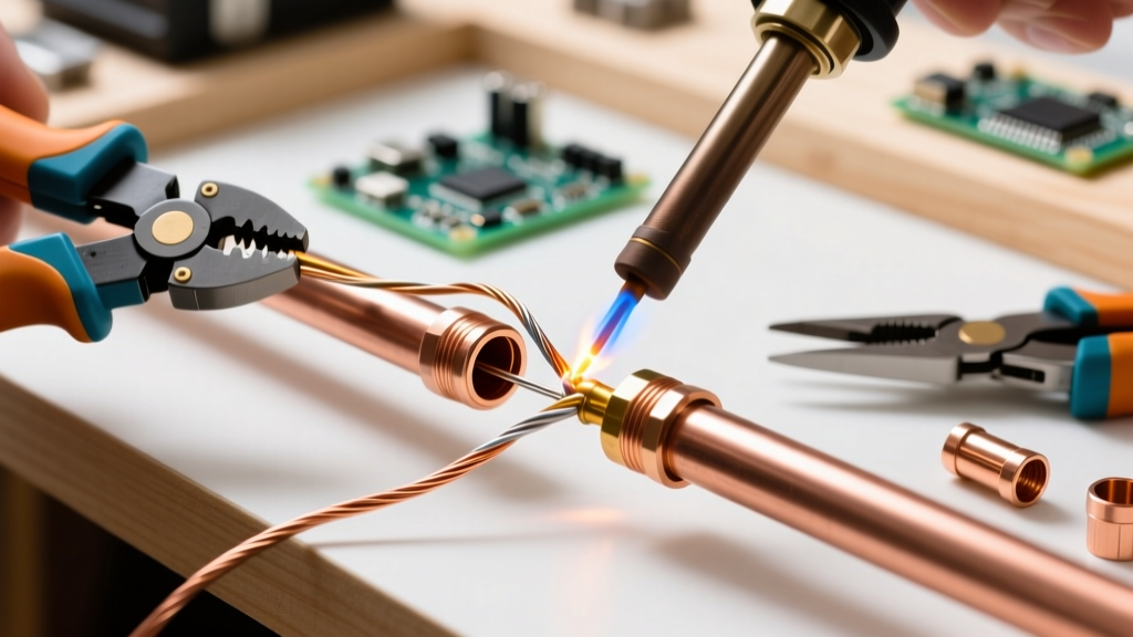
- Mechanical Securing: If splicing two wires, use a Western Union splice or a J-Hook connection. The joint must be mechanically sound before solder is applied. Solder is not glue.
- Apply Flux: Coat the exposed copper with your chosen flux.
- Heat the Mass: Apply the flat of the chisel tip to the wire, not the solder. Allow 1-1.5 seconds for the copper to reach flow temperature.
- Feed the Solder: Touch the solder wire to the junction of the iron tip and the copper wire. If the wire is hot enough, the solder will instantly flash-flow via capillary action.
- Withdraw: Remove the solder first, then slide the iron away. Hold the wire perfectly still for 2-3 seconds until the solder transitions from shiny liquid to a dull, semi-solid state.
IPC-A-610 Criteria and Failure Mode Analysis
According to IPC Standards (specifically IPC-A-610 for wire terminations), a Class 2 or Class 3 soldering wire connection must exhibit a smooth, continuous, concave fillet with visible wetting. The solder should not ball up or hide the wire's contour.
Common Failure Modes
- Cold Joint: Appears dull, grainy, and bulbous. Caused by insufficient heat transfer or moving the wire during the phase-change window. Fix: Re-flux and reflow with a higher mass tip.
- Disturbed Joint: Exhibits a frosted or cracked appearance. Caused by mechanical vibration while the IMC layer is crystallizing. Fix: Secure the wire in a third-hand tool or jig.
- Solder Wicking: Solder creeps under the insulation. This creates a rigid point exactly where the wire needs to flex, leading to metal fatigue and snapping. Fix: Lower your iron temperature, use a smaller tip, and reduce dwell time.
Environmental Protection: Beyond Electrical Tape
Electrical tape is unacceptable for professional wire connections; the adhesive degrades with heat and time, eventually unraveling and exposing the joint to moisture.
Instead, use adhesive-lined heat shrink tubing (e.g., 3M EPS200, ~$15 for a 50-pack). The inner layer of thermoplastic adhesive melts when heated, flowing into the stranded wire and the solder joint, creating a completely waterproof, strain-relieved seal. Slide the tubing over the wire before soldering, position it over the joint, and apply heat from the center outward to push air bubbles out the ends.
Final Thoughts on Wire Reliability
Mastering the soldering wire connection requires respecting the physics of heat transfer and metallurgy. By selecting the correct tip geometry, managing your thermal profile, and adhering to NASA and IPC workmanship standards, you ensure that your wiring harnesses and repairs will survive thermal cycling, vibration, and the test of time. Invest in a quality active-tip station, keep your tips tinned, and never compromise on flux.