
The Critical Synergy: Soldering Wire Material and Thermal Delivery
In modern electronics assembly, the most common cause of defective solder joints is not a lack of operator skill, but a fundamental mismatch between the soldering wire material and the thermal delivery system (the iron, tip geometry, and temperature profile). As we navigate the component density and thermal mass challenges of 2026 PCB designs, treating your solder alloy and your soldering station as isolated variables is a recipe for cold joints, lifted pads, and premature tip degradation.
Every soldering wire material possesses a unique melting point, thermal conductivity, and flux activation threshold. Pairing the correct tip geometry and station wattage to your specific alloy is the cornerstone of IPC-A-610 Class 2 and Class 3 compliance. This guide breaks down the exact tool and technique pairings for the three most dominant soldering wire materials in the DIY and professional electronics space.
Profile 1: Sn63/Pb37 (Eutectic Leaded Solder)
Despite the global push toward RoHS compliance, Sn63/Pb37 remains the undisputed king of hobbyist benches, aerospace prototyping, and legacy repair due to its forgiving nature and lower thermal requirements.
Material Specifications
- Melting Point: 183°C (361°F) - True eutectic (transitions directly from solid to liquid with no plastic state).
- Typical Cost (2026): $35 - $45 per 1lb spool (0.031" diameter).
- Flux Core Pairing: Rosin Mildly Activated (RMA) or standard No-Clean (e.g., Kester 331 or 245).
Tool & Technique Pairing
Because the melting point is relatively low, you do not need aggressive thermal recovery. A standard 40W to 60W ceramic heater station is ideal.
- Optimal Iron Temperature: 315°C to 350°C (600°F - 660°F).
- Recommended Tip Geometry: Standard Chisel (e.g., Hakko T18-D24) or Conical (for 0603 SMD work). The chisel provides maximum surface area contact for through-hole leads.
- Dwell Time: 1.5 to 2.5 seconds per joint.
- Station Match: Weller WES51, Hakko FX-888D, or Pinecil V2 (running at 65W via USB-C PD).
Expert Insight: Never exceed 380°C with Sn63/Pb37. Excessive heat will instantly vaporize the rosin flux core before the alloy can wet the pad, leaving behind a highly oxidized, grainy, and brittle joint that fails visual inspection.
Profile 2: SAC305 (Sn96.5/Ag3.0/Cu0.5 Lead-Free)
SAC305 is the industry standard for commercial RoHS-compliant manufacturing. The addition of silver (Ag) lowers the melting point slightly compared to pure tin-copper alloys and improves mechanical fatigue resistance, but it demands significantly more from your soldering equipment.
Material Specifications
- Melting Point: 217°C - 220°C (423°F - 428°F) - Near-eutectic with a slight pasty range.
- Typical Cost (2026): $75 - $95 per 1lb spool (fluctuates with silver spot prices).
- Flux Core Pairing: High-activity No-Clean or Water-Soluble (e.g., Kester 275 or Indium 5.8HF) to break down stubborn lead-free oxides.
Tool & Technique Pairing
SAC305 has poor wetting characteristics compared to leaded solder. It requires high thermal mass transfer to achieve the necessary intermetallic compound (IMC) layer thickness of 1-3 microns.
- Optimal Iron Temperature: 350°C to 380°C (660°F - 715°F).
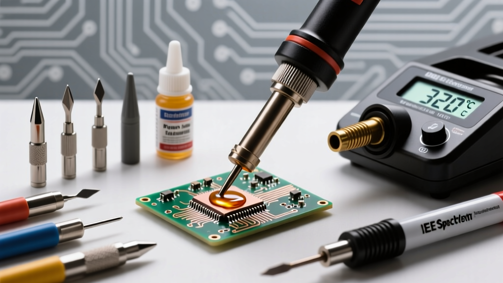
- Recommended Tip Geometry: Bevel (Hoof) or wide Micro-Pencil. A bevel tip (like the JBC C245-945) allows you to 'scoop' the solder and hold a molten pool against high-thermal-mass ground planes.
- Dwell Time: 2.0 to 4.0 seconds. (Do not rush; allow the flux to activate and the pad to reach 220°C).
- Station Match: Cartridge-based systems are mandatory here. JBC CD-2BQF or Pace ADS200. Traditional ceramic heaters suffer from massive thermal droop when touching a ground plane with SAC305.
Profile 3: SN100C (Sn99.3/Cu0.7/Ni/Ge)
Developed as a cost-effective, silver-free alternative to SAC alloys, SN100C includes trace amounts of Nickel (Ni) to reduce copper leaching from your soldering iron tips, and Germanium (Ge) to prevent dross formation and improve wetting.
Material Specifications
- Melting Point: 227°C (441°F).
- Typical Cost (2026): $40 - $55 per 1lb spool.
- Flux Core Pairing: Halogen-free No-Clean (e.g., Kester 285).
Tool & Technique Pairing
- Optimal Iron Temperature: 360°C to 390°C.
- Recommended Tip Geometry: Knife (K-type) or heavy Chisel. The knife tip is exceptional for drag-soldering fine-pitch ICs with SN100C, as the alloy's higher surface tension requires precise mechanical manipulation to prevent bridging.
- Station Match: Metcal PS-900 (RF induction heating) or Hakko FX-951.
Master Pairing Matrix: Alloy to Tool Configuration
Use this reference table to configure your bench before beginning a new project. Data aligns with MIT Edgerton Center's soldering best practices and IPC workmanship standards.
| Soldering Wire Material | Melt Point | Ideal Tip Shape | Iron Temp (°C) | Flux Activation | Tip Life Expectancy |
|---|---|---|---|---|---|
| Sn63/Pb37 (Leaded) | 183°C | Chisel / Conical | 315 - 350°C | 150°C - 180°C | 6+ Months |
| SAC305 (Lead-Free Ag) | 217-220°C | Bevel / Hoof | 350 - 380°C | 180°C - 220°C | 1 - 3 Months |
| SN100C (Lead-Free Ni) | 227°C | Knife / Wide Chisel | 360 - 390°C | 190°C - 230°C | 3 - 5 Months |
| Sn96.5/Ag3.5 (High Rel) | 221°C | Micro-Pencil | 340 - 360°C | 180°C - 210°C | 1 - 2 Months |
The Hidden Variable: Flux Core Activation vs. Iron Temperature
A critical mistake made by intermediate technicians is confusing the melting point of the soldering wire material with the activation temperature of its internal flux core. According to technical data from Indium Corporation, modern no-clean fluxes require a specific thermal profile to break down metal oxides.
If your iron is set to 400°C to compensate for a heavy ground plane, the moment the 0.020" solder wire touches the tip, the flux core flash-boils and vaporizes in less than 0.5 seconds. The alloy melts, but it is now depositing onto an oxidized copper pad without any chemical cleaning agent. The result is a high-contact-resistance joint that looks dull and exhibits poor wetting angles (greater than 90 degrees).
The Technique Fix: Pre-Heating and Secondary Flux
When working with high-thermal-mass boards and SAC305 wire:
- Apply external tacky flux (e.g., Amtech NC-559-V2-TF) to the pad before applying heat.
- Use a board pre-heater (like the Puhui T-8280) set to 100°C to reduce the thermal delta.
- Lower your iron temperature to 360°C to preserve the wire's internal flux core, allowing it to activate simultaneously as the alloy reaches its liquidus state.
Failure Modes: When the Pairing Goes Wrong
1. Tip Cratering and De-Wetting (The SAC305 Leaching Effect)
Lead-free soldering wire materials, particularly those without Nickel (like standard SAC305), are highly aggressive. They actively leach the copper plating right off standard soldering tips. If you use a cheap, thinly plated tip with SAC305 at 380°C, you will experience 'de-wetting'—where the solder refuses to stick to the iron tip—within 48 hours of use. Solution: Always pair lead-free alloys with heavy iron-plated tips (such as the Hakko T18 series or OEM JBC cartridges) and practice 'tinning the tip' with leaded solder before shutting down the station to create a sacrificial barrier.
2. Intermetallic Compound (IMC) Overgrowth
The bond between solder and copper is not just mechanical; it is a metallurgical alloy layer called the Intermetallic Compound (Cu6Sn5). A healthy IMC layer is 1 to 3 microns thick. If you pair a high-temperature iron (400°C+) with a slow-dwelling technique on a small SMD pad, the IMC layer grows too thick (5+ microns). This layer is inherently brittle. The joint will pass visual inspection but will crack under minor mechanical shock or thermal cycling.
Step-by-Step Workflow for Dialing in a New Wire Material
Whenever you spool up a new brand or alloy of soldering wire material, follow this 4-step calibration process:
- Read the TDS: Locate the Technical Data Sheet for the specific wire. Note the liquidus temperature and the recommended iron temperature range.
- Set the Baseline: Set your station to the exact midpoint of the manufacturer's recommended temperature range.
- The Wetting Test: Attempt to tin a bare, oxidized copper wire. If the solder balls up and rolls off, increase the temperature in 10°C increments. If the flux instantly smokes and turns black, decrease by 15°C.
- Verify the Fillet: Solder a test joint on a scrap PCB. Inspect the wetting angle. A perfect pairing yields a smooth, concave fillet with a wetting angle of less than 45 degrees, exhibiting a bright, shiny finish (for leaded) or a smooth, semi-gloss finish (for lead-free).
Conclusion
Mastering electronics assembly requires viewing your soldering wire material not just as a consumable, but as half of a精密 (precision) thermal system. By intentionally pairing your alloy's specific melting dynamics with the correct tip geometry, station wattage, and flux chemistry, you eliminate the guesswork from your workflow. Whether you are dragging SN100C across a fine-pitch QFN or flowing Sn63/Pb37 into heavy gauge transformer leads, respecting the metallurgy of your materials guarantees joints that will outlast the devices they inhabit.